
A valve bottom lining fluid spray device

A substrate and fluid technology, applied in the direction of cleaning methods, cleaning methods and utensils, chemical instruments and methods using gas flow, etc., can solve the inability to effectively eliminate the impact of debris deposition, manage adverse effects of operation, reduce the service life of ball valves, etc. problems, to achieve the effect of preventing water leakage, ensuring sealing and prolonging the service life

Active Publication Date: 2019-05-24
NORTH CHINA UNIV OF WATER RESOURCES & ELECTRIC POWER
View PDF6 Cites 0 Cited by
  • Summary
  • Abstract
  • Description
  • Claims
  • Application Information

AI Technical Summary

Problems solved by technology

During the operation of the pipeline project, the bottom of the ball valve is often silted up due to the deposition of debris and sediment. When the ball valve is closed, the debris and sediment are stuck at the bottom of the rubber pad, causing plastic deformation of the ball valve water-stop rubber pad, reducing the service life of the ball valve. When the diameter is large, the maintenance is complicated, which will have a negative impact on management and operation
[0003] Under the existing technical conditions, the control of the water quality of the water delivery is relatively complicated, and the investment is relatively large
As a part of the water delivery system, pipeline water delivery is often combined with channels, diversion tunnels, aqueducts, etc. to form a complete water transfer system. Due to weather, human factors and other factors, it is inevitable that debris will enter the water body. Only the structure and process of the ball valve can be improved. It is not yet possible to effectively eliminate the impact of debris deposition on the ball valve

Method used


Image

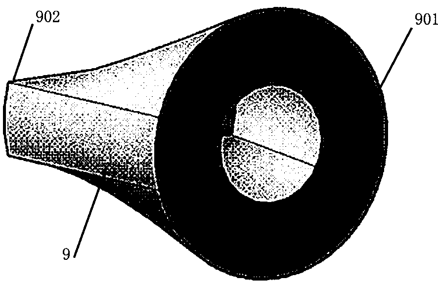
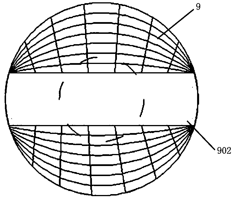
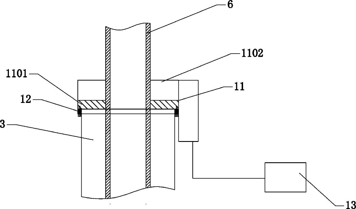
  • A valve bottom lining fluid spray device
  • A valve bottom lining fluid spray device
  • A valve bottom lining fluid spray device

Examples


Embodiment Construction

[0029] In order for those skilled in the art to better understand the technical solutions provided by the present invention, the following will be further elaborated in conjunction with specific embodiments.

[0030] This case will be fully understood by the description of the following embodiments, so that those familiar with the art can complete it, but the embodiments of this case cannot be limited to its implementation form by the following.

[0031] figure 1 It is a schematic diagram of the installation position of a valve backing fluid spraying device of the present invention. The spraying device is arranged on the water delivery pipeline 1, and a ball valve 2 is also arranged on the water delivery pipeline 1 to adjust the water supply flow. Side, used to speed up the water flow at the ball valve 2, characterized in that the spray sweeping device includes a fixing mechanism and an air injection mechanism, the fixing mechanism includes a sealing tube 3, a first sealing va...


PUM


Abstract

The invention provides a valve bottom lining fluid-spraying device. The spraying device is arranged on one side of a ball valve on a water pipe and used for increasing the speed of waterflow in the position of the ball valve. The spraying device comprises a fixing mechanism and an air spraying mechanism. The fixing mechanism comprises a sealing pipe, a first sealing valve and a second sealing valve. The first sealing valve and the second sealing valve are arranged on the sealing pipe. A cavity in the sealing pipe is a mounting channel. The mounting channel is further connected with the air spraying mechanism. The air spraying mechanism comprises an air spraying pipe, a one-way air valve and an external air pump. The air spraying pipe is arranged outside the mounting channel inside the sealing pipe. The first sealing valve and the second sealing valve are clamped to the outer wall of the air spraying pipe. One end of the air spraying pipe extends into the water pipe. The other end of the air spraying pipe is connected to the external air pump. The one-way air valve is further arranged between the air spraying pipe and the external air pump. An included angle is further formed between the air spraying pipe and the water pipe. By means of the valve bottom lining fluid-spraying device, impurities deposited at the bottom of the ball valve on the water pipe can be effectively cleared, and the good opening-closing states of the ball valve are maintained.

Description

technical field [0001] The invention relates to a valve substrate fluid spraying device. Background technique [0002] The uneven distribution of water resources has brought great pressure to my country's social and economic development. A series of water diversion projects represented by the South-to-North Water Diversion Project have made outstanding contributions to alleviating the lack of regional water resources. As the main water supply objects in urban areas, pipeline water supply has outstanding advantages, such as saving land, facilitating construction, and facilitating management. Ball valves are often used to adjust the water supply flow in water transmission lines with large pipe diameters. During the operation of the pipeline project, the bottom of the ball valve is often silted up due to the deposition of debris and sediment. When the ball valve is closed, the debris and sediment are stuck at the bottom of the rubber pad, causing plastic deformation of the bal...

Claims


Application Information

Patent Timeline
Patent Type & Authority Patents(China)
IPC IPC(8): B08B5/02
CPCB08B5/02
Inventor 王博吕艺生张帅超张颜丁振宇聂相田
Owner NORTH CHINA UNIV OF WATER RESOURCES & ELECTRIC POWER
Learn More