
Train passenger secondary collision test system and method

A technology of secondary collision and test system, applied in the field of rail vehicle test, can solve the problems such as the inability to realize the kinematic response and damage analysis of the occupant secondary collision, and achieve the effects of simple structure, good economy and easy realization.

Active Publication Date: 2018-09-07
CENT SOUTH UNIV
View PDF7 Cites 13 Cited by
  • Summary
  • Abstract
  • Description
  • Claims
  • Application Information

AI Technical Summary

Problems solved by technology

[0004] Although the test plan disclosed above can effectively realize the real vehicle impact test of rail vehicles, the data obtained are limited to the car body itself, and the kinematic response and damage analysis of the secondary collision of the occupants cannot be realized. test system

Method used


Image

  • Train passenger secondary collision test system and method
  • Train passenger secondary collision test system and method

Examples


Embodiment 1

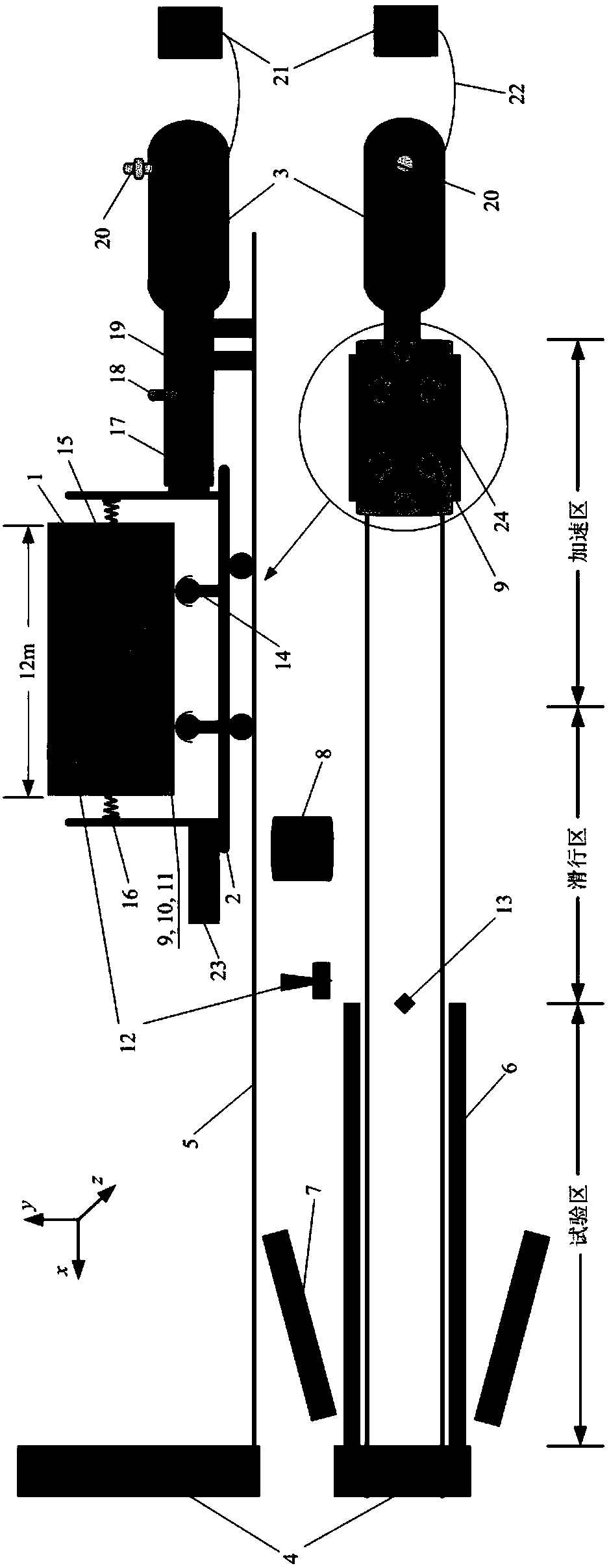
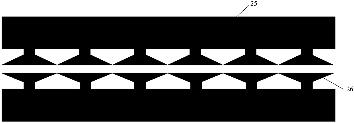
[0021] Such as figure 1 (The upper part is the main view and the lower part is the top view) and figure 2 As shown, the embodiment of the present invention provides a secondary collision test system for train occupants. The test site is set in a large enclosed site. The subgrade, fixed barriers 4 and rails 5 are arranged in the site according to the implementation of the railway, and the roadbed 5 Protective fences are set up meters away, the tracks are laid in the site at the actual interval of the specified railway, and the corresponding rails are divided into sections according to the test stage.

[0022] The zones are the acceleration zone, the taxi zone and the test zone; the acceleration zone is provided by the pneumatic launch power module with the kinetic energy required to drive the car 2, so that the drive car can start running at a set speed, and the compressor performs the gas storage tank 3 When a certain pressure is reached, the trigger mechanism 18 is turned on to...

Embodiment 2

[0050] Corresponding to the above-mentioned embodiment, this embodiment discloses a test method of a train occupant secondary collision test system, including the following steps:

[0051] Step S1. Build a secondary collision test system for train occupants. The system includes a test car, a pneumatic launching power module, a track, a control spring, a hydraulic controller, a driving car with an overload energy-absorbing structure installed on the front end, a first and a second And a third acceleration sensor, a speed control device, a central control module, a pressure sensor, and a displacement sensor; the track is laid on the ground at specified intervals; the driving car is connected to the pneumatic launching power module for driving; The speed control device is installed on both sides of the track in the test area to provide braking; the driving vehicle and the test vehicle are connected vertically by the hydraulic controller, and at least one vertical connection is arrang...


PUM


Abstract

The invention relates to the technical field of rail vehicle testing, and discloses a train passenger secondary collision test system and method. The system of the invention comprises a driving vehicle provided with an overload energy absorbing structure at the front end. Rails are laid on the ground at preset intervals. The driving vehicle is connected with a pneumatic transmitting power module for providing driving. A speed control device is installed on both sides of the rails in a test area to provide braking. The driving vehicle and a test vehicle are longitudinally connected by a hydraulic controller, and at least one first acceleration sensor is disposed at least one joint in the longitudinal direction. The driving vehicle and the test vehicle are laterally connected by a control spring, and at least one second acceleration sensor is disposed at least one joint in the lateral direction. A collision dummy with an unconstrained sitting posture is placed on a seat in the test vehicle compartment, and a pressure sensor, a displacement sensor and a third acceleration sensor are arranged on the dummy.

Description

Technical field [0001] The invention relates to the technical field of rail vehicle testing, and more specifically, to a system and method for a secondary collision test for train occupants. Background technique [0002] The train collision accident seriously threatened the safety of passengers. The secondary collision during the collision is the main cause of occupant casualties, and it is of great significance to the research of occupant passive safety. Real-vehicle crash test is a research method that can truly reflect the collision process of train "single-vehicle + multi-vehicle coupling" and is irreplaceable. Therefore, it is necessary to rely on real-vehicle crash test to carry out occupant secondary collision dynamics and damage analysis during train collision. [0003] The Chinese patent application number is 201410195039.3, titled "Pneumatically Launched Rail Vehicle Real Car Impact Test System", discloses the following technical solutions: "A pneumatically launched rail...

Claims


Application Information

Patent Timeline
IPC IPC(8): G01M17/08G01M7/08
Inventor 彭勇孙成名张洪浩许平姚曙光侯林
Owner CENT SOUTH UNIV
Learn More