3D SCANNER WITH accelerometer

An accelerometer and scanner technology, applied in the field of 3D scanners, can solve problems such as complicated use

Inactive Publication Date: 2018-09-07
库尔塞尔公司
View PDF10 Cites 0 Cited by
  • Summary
  • Abstract
  • Description
  • Claims
  • Application Information

AI Technical Summary

Problems solved by technology

[0006] The disadvantage of these systems is that they are mostly complex to use and require many scans from different angles to obtain the coordinates if a large part of the object to be scanned is to be recorded in 3D or if a complex surface including undercuts is to be scanned

Method used


Image

  • 3D SCANNER WITH accelerometer
  • 3D SCANNER WITH accelerometer
  • 3D SCANNER WITH accelerometer

Examples


Embodiment Construction

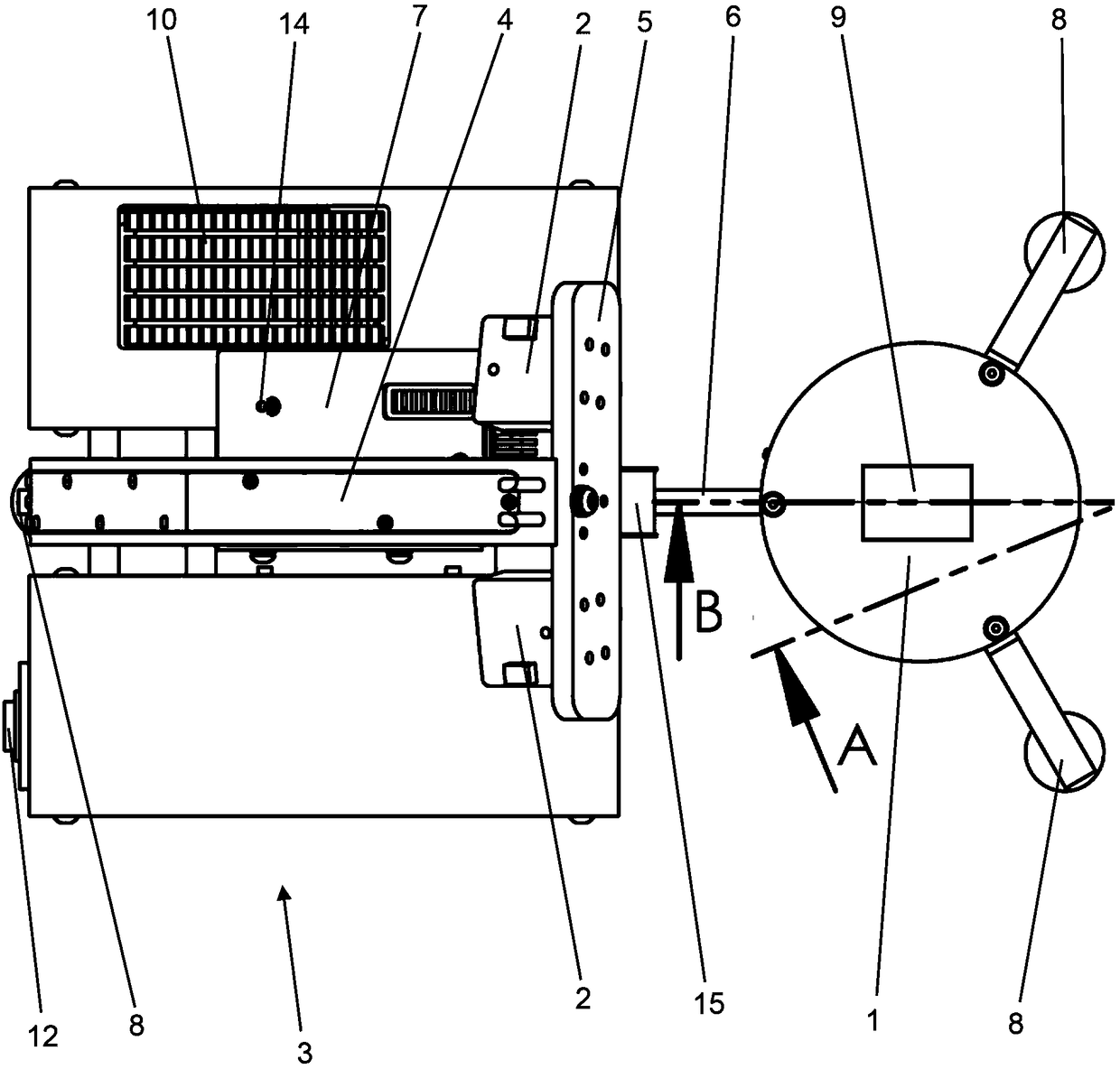
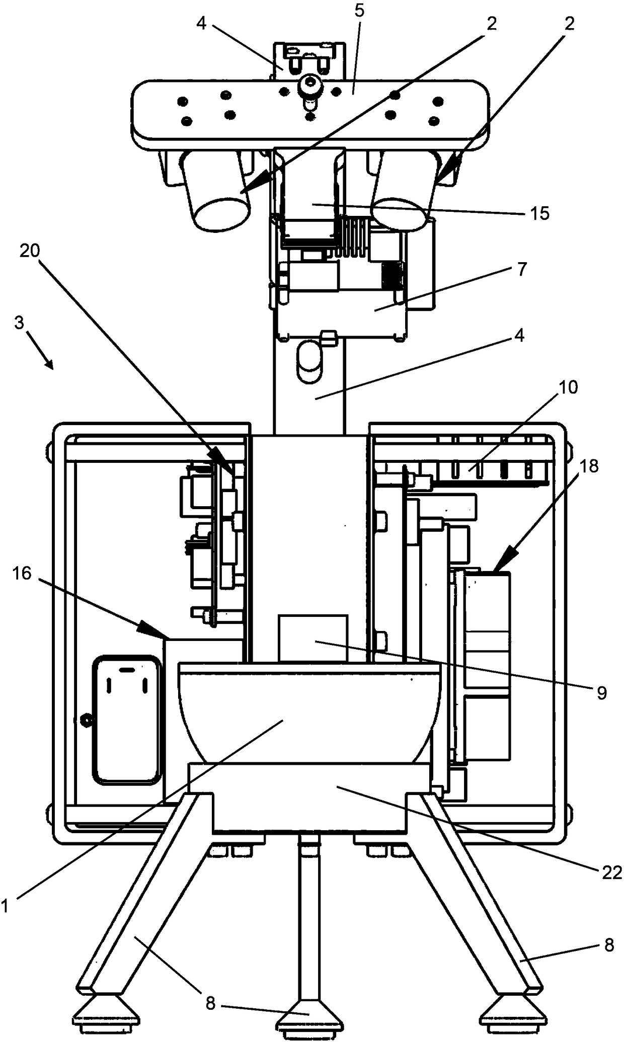
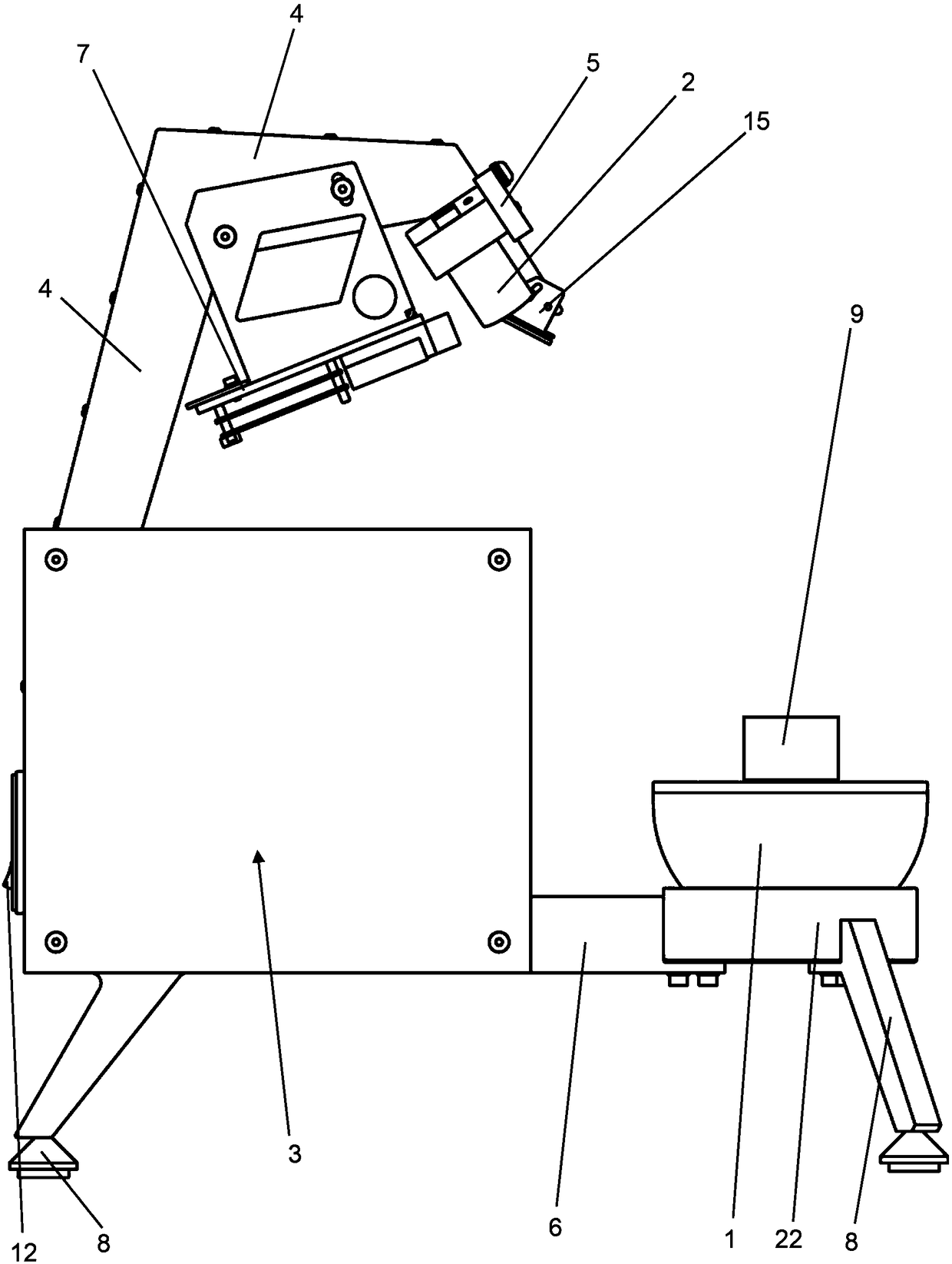
[0072] figure 1 , figure 2 and image 3 A schematic top view, front view and side view of a 3D scanner according to the invention are shown. The 3D scanner comprises a ball stage 1 as a positioning device. The shape of the ball stage 1 is not actually a whole sphere, but a hemisphere or hemisphere, which is freely rotatable about three vertical axes relative to the rest of the 3D scanner. The maximum rotation angle is determined by the upper end of the spherical table 1 (at Figure 2 to Figure 5 in the upper figure 1defined outside the image plane in the direction of the viewer). The platen protrudes beyond the spherical surface, thereby preventing rotation of the spherical table 1 about the two horizontal axes beyond a maximum of 90°. The 3D scanner also includes two cameras 2 capable of recording stereoscopic images from the top of the spherical stage 1 . The main body 3 contains the electronic components of the 3D scanner. The support arm 4 and plate 5 hold and pos...


PUM


Abstract

A 3D scanner with an accelerometer. The invention relates to a 3D scanner comprising at least one scanning module (2, 7) for acquiring three-dimensional (3D) coordinates of a surface of an object (9)and a positioning device (1) on which the object (9) is placeable or fixable, whereby the positioning device (1) is movable relative to the at least one scanning module (2, 7), and the 3D scanner further comprising at least one accelerometer, which is configured to measure a change of the position of the positioning device (1) relative to the scanning module (2, 7), and a first processing unit which is connected to the at least one scanning module (2, 7) and to the positioning device (1) for receiving data. The invention also relates to a method for scanning a surface of an object (9) to acquire three-dimensional (3D) coordinates of the surface.

Description

technical field [0001] The invention relates to a 3D scanner comprising at least one scanning module for acquiring 3D coordinates of a surface of an object. The invention also relates to a method for scanning a surface of an object to obtain three-dimensional (3D) coordinates of the surface. Background technique [0002] Three-dimensional scanners (3D scanners) for scanning 3D surfaces of objects are widely used. A 3D scanner is a device that measures the coordinates (X, Y, Z) of each point or many points on the surface of an object. EP 3081980 A1 discloses an optical scanning device and illumination device which uses a rotation axis to rotate an anisotropically diffusing surface while a coherent light beam is impinging on the anisotropically diffusing surface. US 2016 / 169959 A1 discloses a method and system for acquiring 3D coordinates of a surface of an object by using laser light. From US 2016 / 245918 A1 is known a laser scanner comprising at least one accelerometer and...

Claims


Application Information

Patent Timeline
Patent Type & Authority Applications(China)
IPC IPC(8): G01B11/00G01B11/24G01B11/25
CPCG01B11/005G01B11/2433G01B11/2518G01B11/26G01B21/22G01B5/0004G01B11/2545G01B2210/58G01S17/46G01S17/89G01B11/002G01S17/86G01B11/25G01P15/14G01S17/06G02B26/10G01S7/4817G06T7/521G01B21/20
Inventor L·马卡费里A·格兰迪V·扎米纳拓
Owner 库尔塞尔公司
Why Eureka
Try Eureka