
End effector for automatically disconnecting power line connecting plate

An end effector and connecting plate technology, which is applied in metal processing, metal processing equipment, manufacturing tools, etc., can solve problems such as difficulty for operators, inability to fasten, burning connecting plates, etc., to reduce work items, facilitate operation, reduce dangerous effect

Inactive Publication Date: 2018-09-07
GUANGDONG POWER GRID CO LTD +2
View PDF0 Cites 1 Cited by
  • Summary
  • Abstract
  • Description
  • Claims
  • Application Information

AI Technical Summary

Problems solved by technology

Some factors such as snowfall, blowing vibration and other factors will cause the bus bar to vibrate, which will lead to the loosening of the bolts of the connecting plate of the disconnector, and the contact surface will increase in resistance due to poor contact. Once the resistance increases, the temperature of the connecting plate will increase with the As the temperature rises, the oxidation of the connection board will be strengthened. As the temperature continues to increase, the connection board will be burned and a disconnection accident will occur. The area has caused huge economic losses
[0003] Due to the need to replace the bad connecting plate and bolts after a disconnection accident, if the current of the busbar is cut off and then disconnected, all areas powered by the busbar will be cut off, and the resulting economic losses are unimaginable; Therefore, at present, the disconnection is carried out by manual live work at high altitude, but this kind of defect is mainly caused by manual work at low potential or equipotential live work, but due to the limitation of live work distance, it is difficult for the operator to move, resulting in the failure of the bolts to tighten The torque fails to meet the requirements, and even the wrench socket cannot cover the bolts and cannot be tightened
Moreover, the equipotential live work needs to be approved by the dispatching department, and there is a long approval process, which makes it difficult to tighten loose bolts in time

Method used


Image

  • End effector for automatically disconnecting power line connecting plate
  • End effector for automatically disconnecting power line connecting plate
  • End effector for automatically disconnecting power line connecting plate

Examples


Embodiment 1

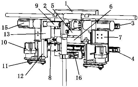
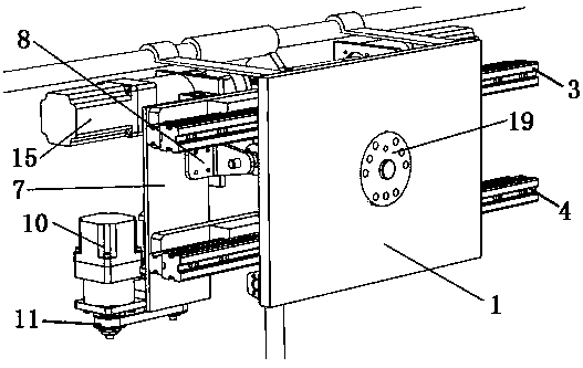
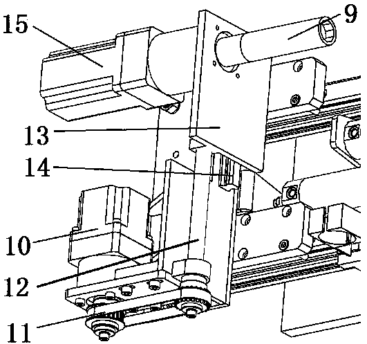
[0034] like figure 1 — Figure 4 As shown, the power line connecting plate automatically disconnects and connects the end effector, including a first base plate 1, one side of the first base plate 1 is connected to the mechanical arm, and the other side of the first base plate 1 is provided with a hook 2 to hang the actuator On the busbar, the other side of the first bottom plate 1 is also provided with a first guide rail slider 3, a second guide rail slider 4, a first pneumatic push rod 5, a second pneumatic push rod 6, and a clamping mechanism; The first guide rail slider 3 and the second guide rail slider 4 are parallel and transversely arranged, and the left and right sides of the first guide rail slider 3 and the second guide rail slider 4 are vertically provided with a second base plate 7; one of the second base plates 7 is connected with the first pneumatic push rod 5 through the fixed plate 8, and the other second bottom plate 7 is connected with the second pneumatic ...


PUM


Abstract

The invention belongs to the technical field of power safety, and particularly relates to an end effector for automatically disconnecting a power line connecting plate. According to the effector, a mechanical arm is arranged on a busbar, and a position is adjusted through the linkage among pneumatic push rods, guide rail sliding blocks and servo motors, so that sleeves and bolts of the connectingplate are aligned accurately, and the sleeves can conveniently disassemble and assemble the bolts of the connecting plate. The effector can fix the disconnecting switch connecting plate and can be quickly and reliably butt-jointed with the bolts, so that a larger output torque is provide, a bolt smashing function is realized, and the bolts are disassembled and assembled.

Description

technical field [0001] The invention belongs to the technical field of electric power safety, in particular to an end effector for automatically disconnecting and connecting a power line connecting plate. Background technique [0002] There are many isolating switch connecting boards distributed on the 110kv high-voltage line of the substation. The isolating switch connecting boards are the connectors for the high-voltage lines to be shunted to various cities and towns. Since the isolating switch connecting boards are exposed outdoors all the year round, they are very vulnerable to environmental and geographical factors. influences. Some factors such as snowfall, blowing vibration and other factors will cause the bus bar to vibrate, which will lead to the loosening of the bolts of the connecting plate of the disconnector, and the contact surface will increase in resistance due to poor contact. Once the resistance increases, the temperature of the connecting plate will increa...

Claims


Application Information

Patent Timeline
IPC IPC(8): B23P19/06B23P19/00
CPCB23P19/06B23P19/006
Inventor 汤振鹏吴建锋裴运军陈劲蔡爱金何兴华陈文鸿蒋鑫
Owner GUANGDONG POWER GRID CO LTD
Learn More