Kitchen ventilator and working method thereof

A working method and technology of a range hood, which are applied in the fields of removing oil fume, heating method, and household heating, etc., can solve the problems of wind resistance, low wind pressure of the range hood, troublesome operation, etc., so as to overcome the influence of wind resistance, high decontamination efficiency, wind foot effect

Inactive Publication Date: 2018-09-04
CHANGLE LIZHI IND DESIGN CO LTD
View PDF6 Cites 1 Cited by
  • Summary
  • Abstract
  • Description
  • Claims
  • Application Information

AI Technical Summary

Problems solved by technology

[0002] The range hood needs to be cleaned regularly. Simple cleaning cannot remove the oil stains. To clean the range hood, a professional cleaning agent must be used for cleaning. The degreasing effect of the range hood is poor, which cannot meet the needs of cleaning. In addition, there is also the disadvantage that the range hood has a low wind pressure and is greatly affected by wind resistance.

Method used


Image

  • Kitchen ventilator and working method thereof
  • Kitchen ventilator and working method thereof

Examples


Embodiment Construction

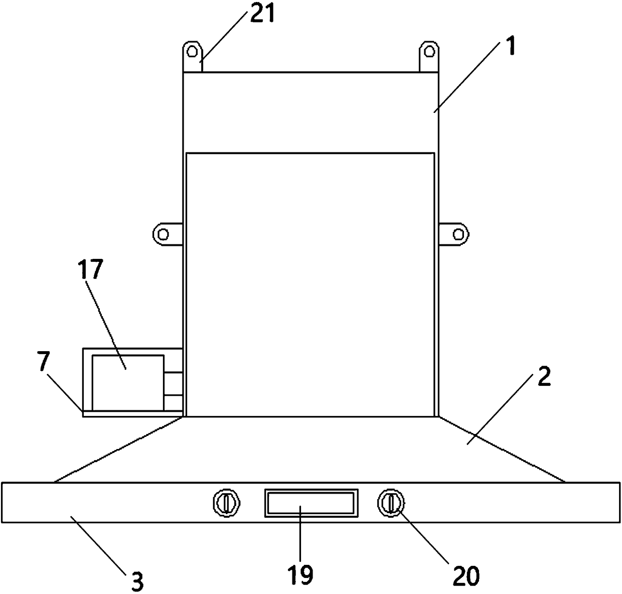
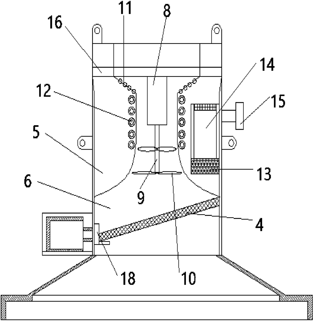
[0013] Such as Figure 1-Figure 2 As shown, a range hood includes a casing 1, a conical cover 2, and a smoke collection chamber 3, and the smoke collection chamber 3 is used to collect oil fumes. The casing 1, the conical cover 2, and the smoke collection chamber 3 are all formed from sheet metal. They are connected sequentially from top to bottom. An oil-gas separation cover 4 arranged obliquely is clamped between the lower inner walls of the casing 1. The angle between the oil-gas separation cover 4 and the horizontal plane is 10 degrees to 30 degrees. The upper inner wall of the casing 1 is provided with The trumpet-shaped cavity 5 is used to reduce wind resistance and provide installation space at the same time. The guide air duct 6 is formed between the cavity 5. The top of the cavity 5 is horizontally provided with a mounting frame 7. The mounting frame 7 The middle part of the lower surface is fixed with a drive motor 8, and the motor shaft 9 is arranged below the drive...


PUM


Abstract

The invention discloses a kitchen ventilator and a working method thereof. The kitchen ventilator comprises an outer shell, a conical housing and a fume collection cavity. The outer shell, the conicalhousing and the fume collection cavity are each molded from sheet metal and connected in sequence from top to bottom. An oil-gas separation housing is connected between the inner walls of the lower portion of the outer shell in a clamped manner, wherein the oil-gas separation housing is arranged in an inclined manner. The included angle between the oil-gas separation housing and the horizontal plane ranges from 10 degrees to 30 degrees. A horn-shaped cavity is formed in the inner wall of the upper portion of the outer shell. A flow guiding air channel is formed in the middle of the cavity. Amounting bracket is horizontally arranged at the top end of the cavity. A driving motor is fixedly arranged in the middle of the lower surface of the mounting bracket. Airflow is discharged out of theflow guiding air channel. By means of the oil-gas separation housing, most oil stains are blocked; by means of an ultrasonic generator, a cleaning agent in a cleaning agent box is atomized; the driving motor rotates reversely at the low speed, and the cleaning agent obtained after atomization is driven to flow through the flow guiding air channel; a heater heats, so that the oil stains fall off,flow along the inclined oil-gas separation housing and enter an oil collection bottle through a connecting nozzle; stain removal efficiency is high; and fan blades which are mounted on two layers arehigh in wind power, and the wind resistance influence can be better overcome.

Description

technical field [0001] The invention relates to the technical field of range hoods, in particular to an automatic degreasing range hood and a working method thereof. Background technique [0002] The range hood needs to be cleaned regularly. Simple cleaning cannot remove the oil stains. To clean the range hood, a professional cleaning agent must be used for cleaning. The degreasing effect of the range hood is poor, which cannot meet the needs of cleaning. In addition, there is also the disadvantage that the range hood has a low wind pressure and is greatly affected by wind resistance. Contents of the invention [0003] The purpose of the present invention: to provide a range hood with automatic degreasing and its working method. The atomized cleaning agent flows through the diversion air channel, and the heater heats it to make the oil stain fall off. The decontamination efficiency is high, and the fan installed in double layers The blades are powerful enough to better ov...

Claims


Application Information

Patent Timeline
Patent Type & Authority Applications(China)
IPC IPC(8): F24C15/20
CPCF24C15/20F24C15/2057
Inventor 不公告发明人
Owner CHANGLE LIZHI IND DESIGN CO LTD
Why Eureka
Try Eureka