
Composite wall for passive ultra-low energy buildings

A technology for composite walls and buildings, applied in passive houses, buildings, building components, etc., can solve the problems of high maintenance and operation costs, unsatisfactory application effects, etc., reduce operation and use costs, improve energy transfer efficiency, The effect of reducing complexity

Active Publication Date: 2019-09-03
TIANJIN UNIV
View PDF6 Cites 0 Cited by
  • Summary
  • Abstract
  • Description
  • Claims
  • Application Information

AI Technical Summary

Problems solved by technology

Although phase change materials can store and release cold and heat to reduce the heating and cooling loads caused by the envelope structure, their application effect is not ideal in severe cold areas with large indoor and outdoor temperature differences.
As for the heat-activated building system (embedded pipe system), it can reduce building energy consumption and provide energy for the building by embedding pipes with heat-carrying and cooling-carrying media in the envelope and using the building as a heat storage body purpose, but this technology is still one of the active energy-saving measures, so its maintenance and operation costs are still high

Method used


Image

  • Composite wall for passive ultra-low energy buildings
  • Composite wall for passive ultra-low energy buildings
  • Composite wall for passive ultra-low energy buildings

Examples


Embodiment Construction

[0025] The present invention will be described in detail below in conjunction with the accompanying drawings and specific embodiments.

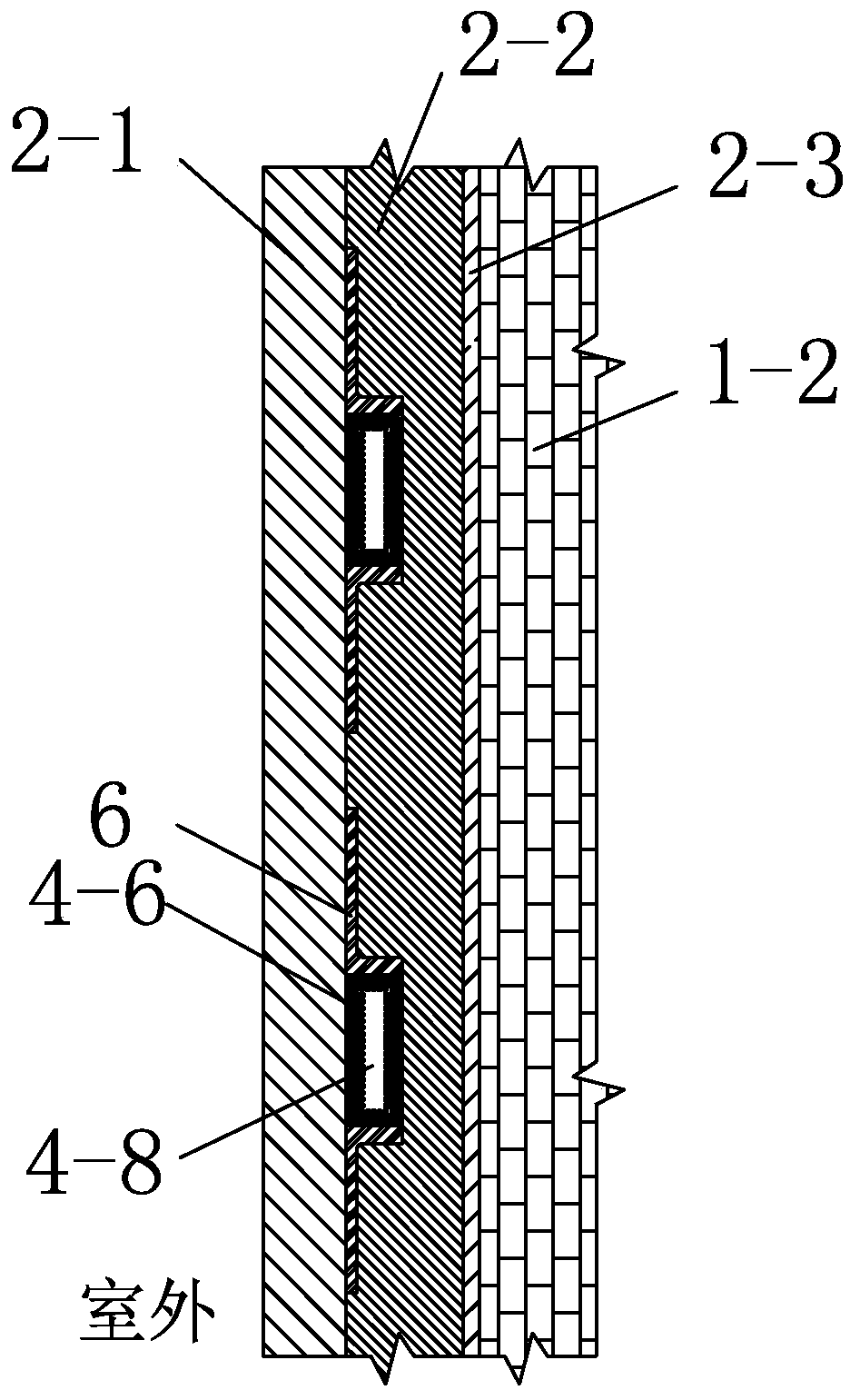
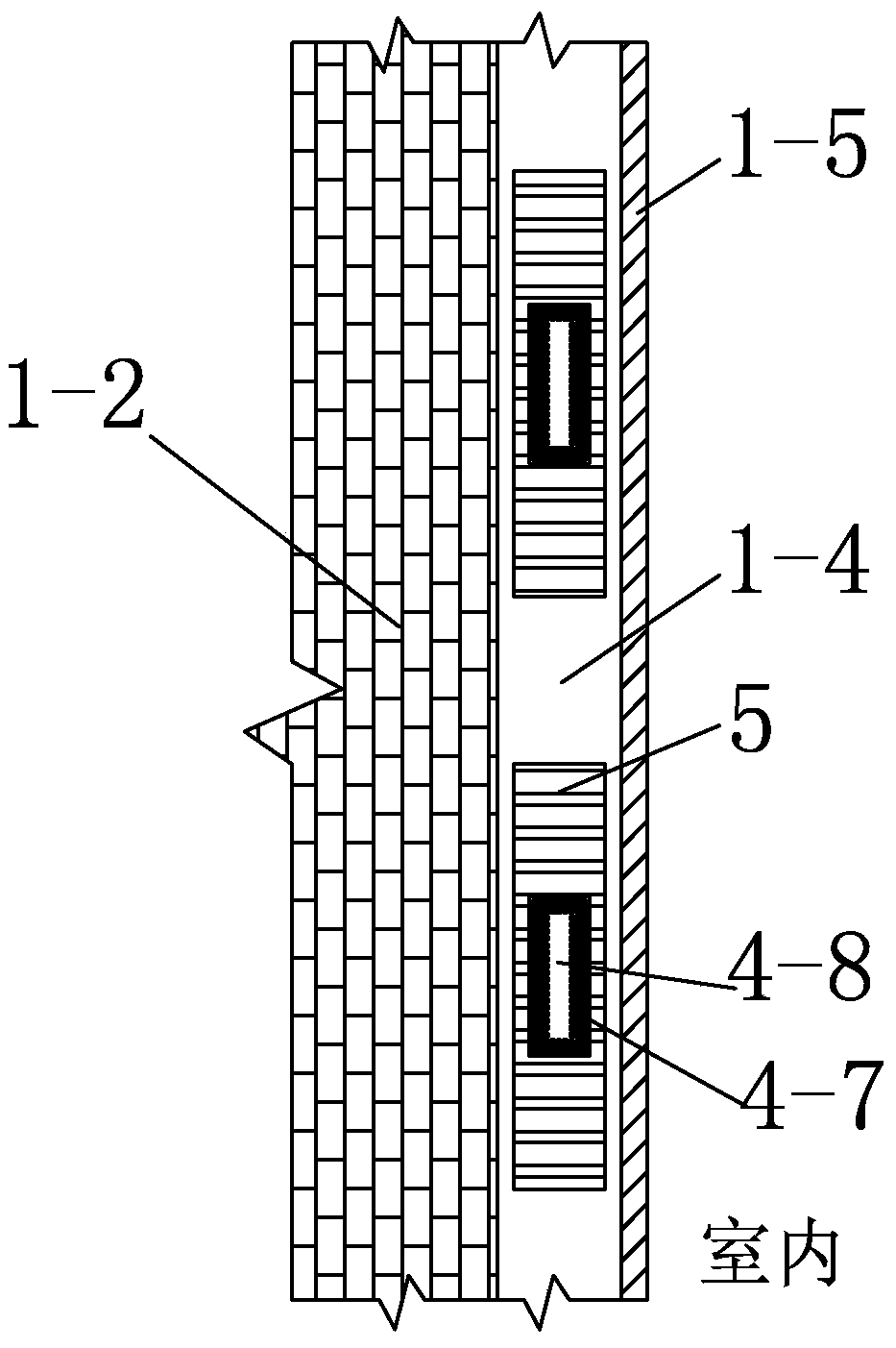
[0026] The schematic diagram of the composite wall for passive ultra-low energy consumption buildings of the present invention is as follows Figure 1-Figure 3 As shown, it includes a composite wall 1 , an outer wall member 2 and a plurality of loop heat pipe units. The composite wall 1 is sequentially composed of an external plastering layer 1-1, a wall insulation layer 1-2, a foundation wall 1-3, an energy storage layer 1-4, and an internal plastering layer from outdoor to indoor. 1-5. The outer wall member 2 is inlaid and fixed on the outer wall plastering layer 1-1 and the wall insulation layer 1-2. The outer member of the wall is a photovoltaic module 2-1, a member insulation layer 2-2 and a substrate 2-3, which are integrated from the outside to the inside. Each loop heat pipe unit includes a closed circulation pipeline composed of a...


PUM


Abstract

The invention discloses a passive composite wall for an ultra-low energy construction. The passive composite wall reduces the complexity of an energy supply system of the ultra-low energy constructionand reduces the operation and use costs. The passive composite wall comprises a composite wall body, a wall body outer side member and a plurality of loop heat pipe units; the wall body outer side member is an integrated structure composed of a photovoltaic module, a member heat-insulation layer and a base plate from outside to inside; each loop heat pipe unit comprises a closed circulation pipeline and a control valve, wherein each closed circulation pipeline is composed of a hollow outdoor end heat transfer pipe, an upper heat transfer pipe, an indoor end heat transfer pipe and a lower heattransfer pipe; an outdoor end wick corresponding to the back of the photovoltaic module is arranged in each outdoor end heat transfer pipe, each indoor end heat transfer pipe is internally provided with an indoor end wick, and the centers of each outdoor end wick and each indoor end wick are working medium flow channels; and the control valve is installed on the closed circulation pipeline. The passive composite wall makes full use of low-grade solar energy and night environment cold energy to supply and store cold energy and heat energy for the ultra-low energy construction, and the operation and use costs are reduced.

Description

technical field [0001] The invention relates to the technical field of building energy conservation, in particular to a composite wall structure for passive ultra-low energy consumption buildings. Background technique [0002] At present, my country's building energy consumption accounts for about 40% of the total energy consumption of the society, and the proportion is even higher in the central and eastern regions where the population is denser and the economy is more developed. Ecological civilized society has important practical significance. As we all know, improving the performance of the building energy supply system and reducing the load of the building itself are the two main measures for building energy conservation. On the one hand, traditional active energy supply systems such as coal-fired boilers, heat pump systems or gas-fired tri-generation systems are more complex, costly, and less environmentally compatible, and are more suitable for energy supply for large...

Claims


Application Information

Patent Timeline
Patent Type & Authority Patents(China)
IPC IPC(8): E04B2/00E04B1/76F28D15/04
CPCE04B1/762E04B2/00F28D15/043Y02A30/00Y02B30/90
Inventor 朱丽杨洋陈萨如拉孙勇
Owner TIANJIN UNIV
Learn More