Steel-aluminum composite conductor rail and manufacturing method thereof

A steel-aluminum composite and conductive rail technology, applied in the field of conductive rails, can solve the problems of large cross-sectional shape limitations, large cross-sectional shape limitations, inconsistent lengths of steel and aluminum, etc., to reduce the penetration resistance of the wear-resistant layer and save energy The effect is obvious and the effect of reducing the conduction resistance

Active Publication Date: 2018-09-04
洛阳固岳轨道科技有限公司
View PDF5 Cites 0 Cited by
  • Summary
  • Abstract
  • Description
  • Claims
  • Application Information

AI Technical Summary

Problems solved by technology

[0004] The overall dimensional accuracy is poor, the flatness of the working surface is poor, and the joints between adjacent rail bodies are uneven after installation on the line, and impact and abnormal noise are easy to occur during operation; three dovetail grooves are used for rolling lamination between steel and aluminum , along the length direction is only restricted by the friction force after pressing, and the inconsistent length of steel and aluminum is prone to appear after repeated thermal expansion and contraction; due to process limitations, the fixed length is limited, generally no more than 15 meters, and the cross-sectional shape is limited. Big;
[0005] The stainless steel wear-resistant body of the I-shaped rail is welded in the middle part after being snapped in on both sides of the aluminum substrate. Inconsistent lengths of steel and aluminum; due to process limitations, the length of cut-to-length is limited, generally no more than 15 meters, and the cross-sectional shape is limited

Method used


Image

  • Steel-aluminum composite conductor rail and manufacturing method thereof
  • Steel-aluminum composite conductor rail and manufacturing method thereof

Examples


Embodiment 1

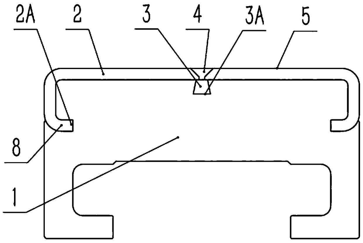
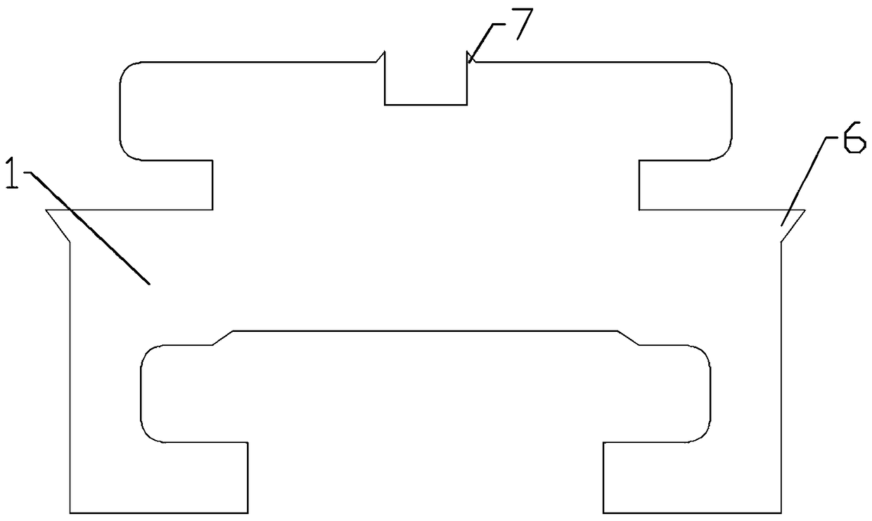
[0026] A steel-aluminum composite conductor rail, such as figure 1 As shown, it includes an aluminum substrate 1, a plate-shaped wear-resistant body 2 is installed on the upper end of the aluminum substrate 1, and wear-resistant body slots are processed on both sides of the upper end of the aluminum substrate 1. The wear-resistant body slot is a groove, and the wear-resistant body includes two The wear-resistant monomer is made of stainless steel with a thickness of 4mm. The cross-section of the wear-resistant monomer is L-shaped. The lower end of the wear-resistant monomer is bent inward to form a bending part 8, and the edge of the bending part 8 The wear-resistant single tooth 2A is uniformly processed. The cross-section of the wear-resistant single tooth 2A is triangular. There is a first groove matching the wear-resistant single tooth. In this embodiment, the first groove is formed by the wear-resistant single tooth extrusion process of the wear-resistant single body to t...


PUM


Abstract

The invention relates to conductor rails for rail transit, in particular to a steel-aluminum composite conductor rail and a manufacturing method thereof. The steel-aluminum composite conductor rail comprises an aluminum base and is characterized in that a plate-shaped wear-resistant body is arranged at the upper end of the aluminum base, wear-resistant body clamp grooves are arranged in two sidesof the upper end of the aluminum base, the wear-resistant body comprises two single wear-resistant body parts, the section of each single wear-resistant body part is L-shaped, the lower end of each single wear-resistant body part bends inwardly to form a bent part, single wear-resistant body part teeth are evenly arranged at the edge of each bent part, a central-embedded-strip mounting groove is formed in the upper end of the aluminum base, a central embedded strip is arranged in the central-embedded-strip mounting groove, the two sides of the central embedded strip compresses against the lateral wall of the central-embedded-strip mounting groove, and the lower end of the central embedded strip is evenly provided with central-embedded-strip teeth. The steel-aluminum composite conductor rail is manufactured through insertion, rolling, welding, milling and cutting. The manufactured steel-aluminum composite conductor rail is tight and firm in bidirectional combination, high in overall dimensional precision, flexible and diversified in section shape and simple and efficient in manufacturing process.

Description

technical field [0001] The invention relates to a conductive rail for rail transit, in particular to a steel-aluminum composite conductive rail and a manufacturing method thereof. Background technique [0002] Existing steel-aluminum composite conductive rails mainly include C-shaped rails and I-shaped rails. Its main disadvantages are: [0003] C-rail [0004] The overall dimensional accuracy is poor, the flatness of the working surface is poor, and the joints between adjacent rail bodies are uneven after installation on the line, and impact and abnormal noise are easy to occur during operation; three dovetail grooves are used for rolling lamination between steel and aluminum , along the length direction is only restricted by the friction force after pressing, and the inconsistent length of steel and aluminum is prone to appear after repeated thermal expansion and contraction; due to process limitations, the fixed length is limited, generally no more than 15 meters, and t...

Claims


Application Information

Patent Timeline
IPC IPC(8): B60M1/30
CPCB60M1/302
Inventor 刘宗庆
Owner 洛阳固岳轨道科技有限公司
Why Eureka
Try Eureka