
A rack and pinion transmission material receiving device for a die-cutting machine

A technology of rack and pinion and feeding device, applied in non-rotational vibration suppression, metal processing and other directions, can solve the problems of semi-finished products, inability to easily adjust the tilt position, etc., and achieve the effect of improving quality, reducing temperature and avoiding damage

Active Publication Date: 2020-11-10
安徽捷盛科技有限公司
View PDF7 Cites 0 Cited by
  • Summary
  • Abstract
  • Description
  • Claims
  • Application Information

AI Technical Summary

Problems solved by technology

[0003] After the die-cutting machine is finished, it is necessary to carry out feeding, and the existing feeding device is integrated, so it is not possible to adjust its tilt position conveniently, and after the die-cutting machine is finished, the temperature of some semi-finished products is relatively high. Under certain circumstances, the semi-finished product will have a certain impact on the semi-finished product when it slides on the material receiving plate

Method used


Image

  • A rack and pinion transmission material receiving device for a die-cutting machine
  • A rack and pinion transmission material receiving device for a die-cutting machine
  • A rack and pinion transmission material receiving device for a die-cutting machine

Examples


Embodiment Construction

[0021] The technical solution of this patent will be further described in detail below in conjunction with specific embodiments.

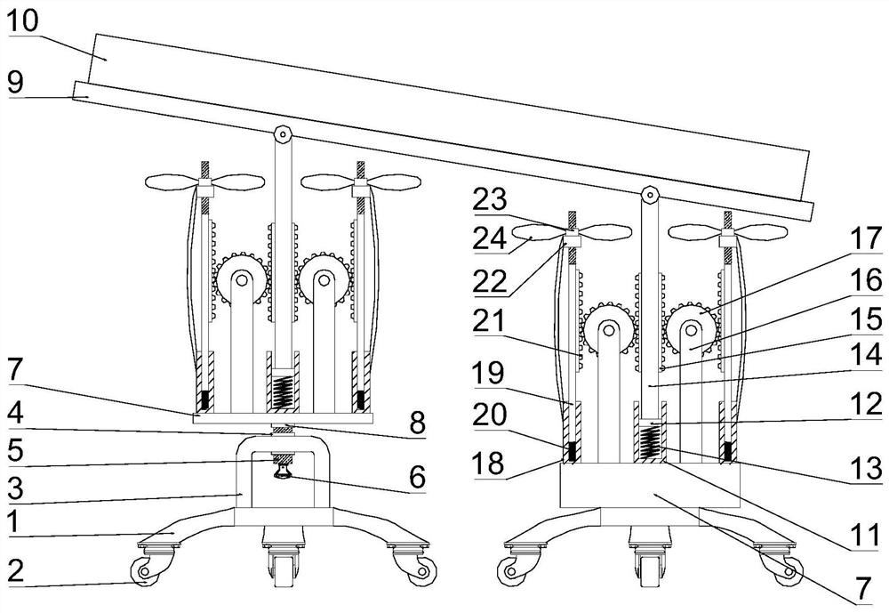
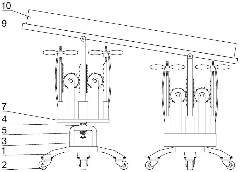
[0022] see Figure 1-2 , a rack and pinion transmission material receiving device for a die-cutting machine, comprising a material receiving plate 9 and a bottom plate 1, the bottom plate 1 is provided with a pair, and the upper part of the bottom plate 1 on the left side is fixedly connected with an inverted U-shaped The mounting frame 3 is fixedly nested with a threaded buckle 4 on the mounting frame 3, and the inside of the threaded button 4 is provided with an internal thread, and the threaded buckle is internally screwed with a threaded column 5, and the upper part of a pair of base plates 1 is provided with a fixed plate 7, which is located at A bearing 8 is installed on the lower surface of the fixed plate 7 on the left side, and the upper polished rod portion of the threaded column 5 is installed in the 8 mounting holes of the bearing, and ...


PUM


Abstract

The invention discloses a gear and rack driving receiving device for a die cutting machine. The gear and rack driving receiving device comprises a receiving plate and a pair of bottom plates. A rotation handle is manually rotated, so that a threaded column moves, and therefore a fixed plate positioned on the left side can move. Thus, the oblique angle of the receiving plate can be conveniently regulated, and the sliding speed of a semi-finished product on the receiving plate is conveniently regulated. The operation is simple and fast. A guide block moves down, a gear is rotated under the matching of a first rack and the gear, therefore a second rack moves up, a screw rod moves up, and a screw rod nut is rotated to drive a fan impeller to rotate. Thus, the heat of the semi-finished productpositioned on the upper part of the receiving plate is dissipated, the temperature of the semi-finished product drops, and the quality of the semi-finished product is improved. A first spiral spring is compressed and a second spiral spring is extended, thus the receiving plate has an effect of shock absorption, and the damage on the semi-finished product caused by too large impact force during blanking is avoided.

Description

technical field [0001] The invention relates to the technical field of die-cutting machines, in particular to a rack and pinion transmission material receiving device for a die-cutting machine. Background technique [0002] Die-cutting machine is also called beer machine, cutting machine, CNC stamping machine, mainly used for die-cutting of some corresponding non-metallic materials, self-adhesive, EVA, double-sided adhesive, electronics, mobile phone rubber pad, etc. breaking), indentation and bronzing operations, lamination, automatic waste discharge, die-cutting machines use steel knives, metal molds, steel wires (or templates carved from steel plates), and apply a certain pressure through the embossing plate to print or The cardboard is rolled and cut into certain shapes. It is an important equipment for post-press packaging processing and molding. The working principle of the die-cutting machine is to use a die-cutting knife, a steel knife, a metal mold, a steel wire (...

Claims


Application Information

Patent Timeline
Patent Type & Authority Patents(China)
IPC IPC(8): B26D7/32F16F15/06
CPCB26D7/32F16F15/06
Inventor 巢旭阳
Owner 安徽捷盛科技有限公司
Learn More