Eureka AIR delivers breakthrough ideas for toughest innovation challenges, trusted by R&D personnel around the world.

Satellite image ground object marking device and method

A technology of satellite images and ground objects, which is applied in the field of remote sensing, can solve problems such as poor applicability, inconsistent physical representations, and difficult physical representations of ground objects, achieving the effect of high accuracy, low definition requirements, and fast ground object labeling

Inactive Publication Date: 2018-08-31
北京佳格天地科技有限公司
View PDF7 Cites 7 Cited by
  • Summary
  • Abstract
  • Description
  • Claims
  • Application Information

AI Technical Summary

Problems solved by technology

The above-mentioned automatic labeling method has the following problems: the error is large, and the R value, G value, or B value of the same ground object exceeds the system due to reasons such as different regions, different shooting times, different shooting angles, and its own color. The set value range of the R value, G value, and B value of the feature makes it impossible to label, or even wrongly label
The above-mentioned automatic labeling method has the following problems: 1. The error is large, and it is difficult to accurately define the physical representation of the ground object. The same ground object is different due to different regions, different shooting times, different shooting angles, and its own color. The physical representation of itself does not match the physical representation in the definition, resulting in the failure to label, or even wrong labeling; 2. The requirements for satellite images are relatively high. Due to the need to extract the physical representation of ground objects, satellite images are required to have a higher resolution 3. Poor applicability. For satellite images in different regions, different physical representation definitions for ground features are required.

Method used


Image

  • Satellite image ground object marking device and method
  • Satellite image ground object marking device and method
  • Satellite image ground object marking device and method

Examples


Embodiment Construction

[0057] In order to understand the above-mentioned purpose, features and advantages of the present invention more clearly, the present invention will be further described in detail below in conjunction with the accompanying drawings and specific embodiments. It should be noted that, in the case of no conflict, the embodiments of the present application and the features in the embodiments can be combined with each other.

[0058] In the following description, many specific details are set forth in order to fully understand the present invention. However, the present invention can also be implemented in other ways different from those described here. Therefore, the protection scope of the present invention is not limited by the specific details disclosed below. EXAMPLE LIMITATIONS.

[0059] The following discussion provides various embodiments of the invention. Although each embodiment represents a single combination of the invention, different embodiments of the invention may b...


PUM


Abstract

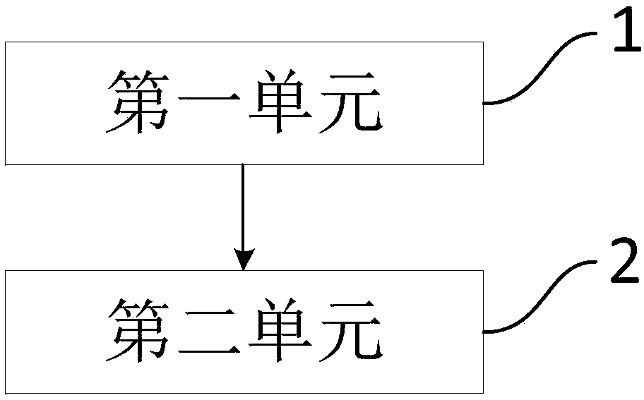
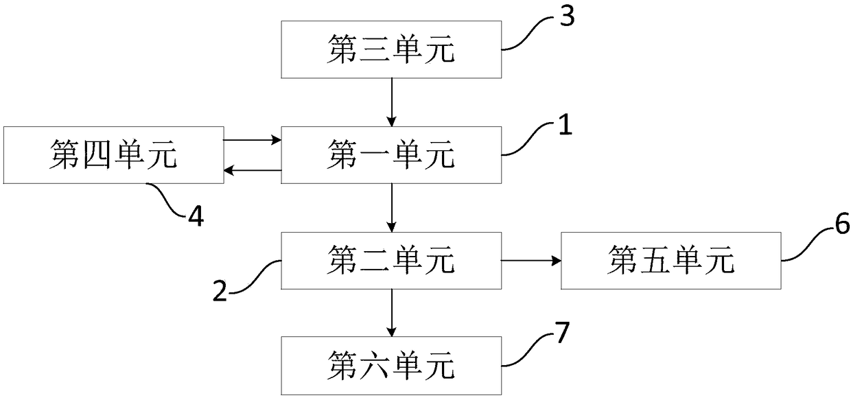
The invention provides a satellite image ground object marking device and method; the satellite image ground object marking device comprises the following parts: a first unit configured to obtain a training set and extract ground object marking features of the training set, thus forming a training model, wherein the training set comprises a plurality of first satellite images with finished groundobject marking; a second unit configured to obtain the training model and marking ground objects in the second satellite image according to the training model. The satellite image ground object marking method comprises the following steps: extracting ground object marking features of the training set, forming the training model; marking the ground objects in the second satellite image according tothe training model. The satellite image ground object marking device and method can automatically mark the satellite image ground objects, can fast mark ground objects with high accuracy, and have low sharpness requirements for the satellite images.

Description

technical field [0001] The invention relates to the technical field of remote sensing, in particular, to a device and method for marking ground objects of satellite images. Background technique [0002] The description of the background technology of the present invention belongs to the relevant technology related to the present invention, and is only used to illustrate and facilitate the understanding of the content of the present invention. prior art on the filing date. [0003] Marking the ground objects (roads, houses, water bodies, etc.) in satellite images is an important topic in the field of satellite images. At present, most of the ground features are marked manually; Labeling, for example, in a frame of satellite image, the road is marked as "1", the house is marked as "2", and the water body is marked as "3". The accuracy of manual labeling is high, but the efficiency is extremely low, and it is time-consuming and labor-intensive to label ground objects in a lar...

Claims


Application Information

Patent Timeline
Patent Type & Authority Applications(China)
IPC IPC(8): G06K9/62G06N3/04
CPCG06N3/045G06F18/241G06F18/214
Inventor 史红欣张弓顾竹
Owner 北京佳格天地科技有限公司
Why Eureka
Eureka Blog
Learn More