Eureka AIR delivers breakthrough ideas for toughest innovation challenges, trusted by R&D personnel around the world.

Unmanned aerial vehicle landing method and device, parking apron and electronic equipment

A UAV and apron technology, applied in the direction of landing aids, non-electric variable control, vehicle position/route/altitude control, etc., can solve the problems that UAVs cannot complete accurate landings, UAVs cannot be recognized, etc.

Pending Publication Date: 2021-12-31
GUANGZHOU XAIRCRAFT TECH CO LTD
View PDF0 Cites 0 Cited by
  • Summary
  • Abstract
  • Description
  • Claims
  • Application Information

AI Technical Summary

Problems solved by technology

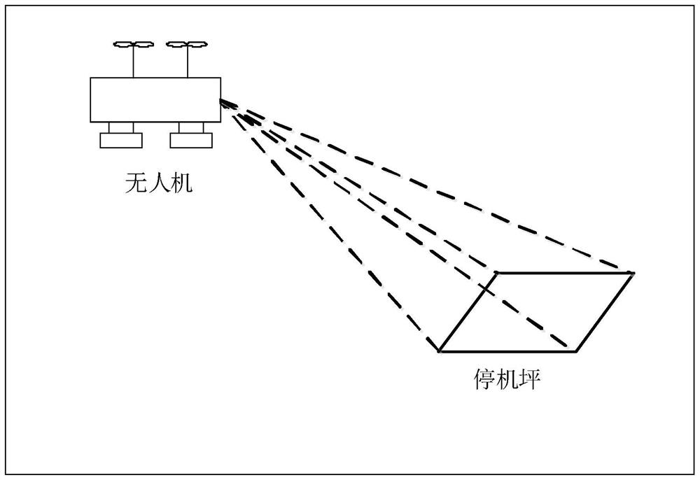
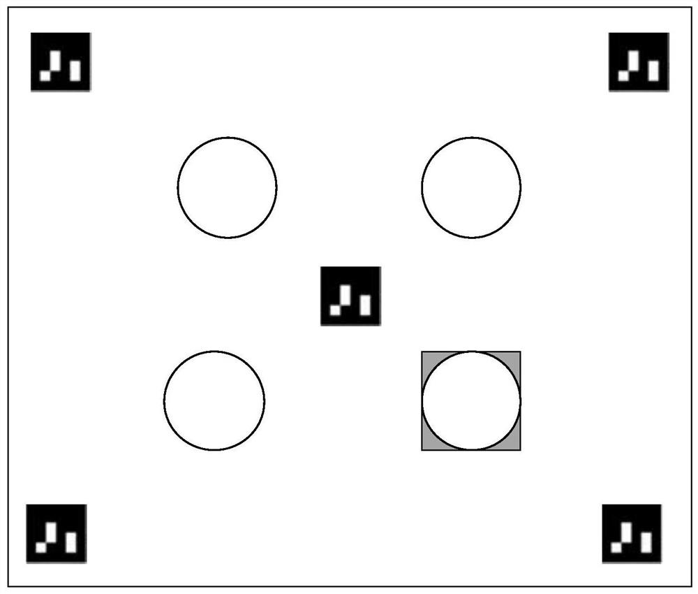
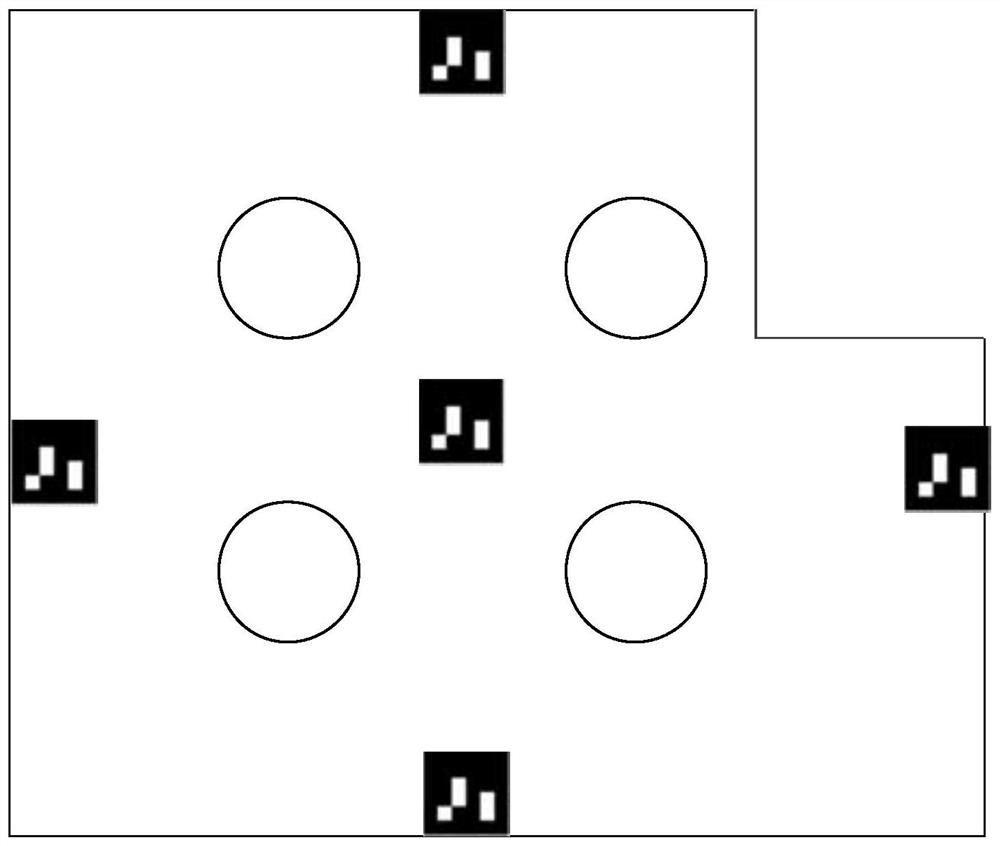
[0005] The purpose of this application is to provide a UAV landing method, device, apron and electronic equipment for the above-mentioned deficiencies in the prior art, so as to solve the problem that the UAV cannot recognize the two-dimensional space on the apron in the prior art. The problem that the drone cannot complete the accurate landing caused by the problem of the code icon

Method used


Image

  • Unmanned aerial vehicle landing method and device, parking apron and electronic equipment
  • Unmanned aerial vehicle landing method and device, parking apron and electronic equipment
  • Unmanned aerial vehicle landing method and device, parking apron and electronic equipment

Examples


Embodiment Construction

[0121] In order to make the purpose, technical solutions and advantages of the embodiments of the present application clearer, the technical solutions in the embodiments of the present application will be clearly and completely described below in conjunction with the drawings in the embodiments of the present application. It should be understood that the appended The figures are only for the purpose of illustration and description, and are not used to limit the protection scope of the present application. Additionally, it should be understood that the schematic drawings are not drawn to scale. The flowcharts used in this application illustrate operations implemented in accordance with some embodiments of the application. It should be understood that the operations of the flowcharts may be performed out of order, and steps that have no logical context may be performed in reverse order or concurrently. In addition, those skilled in the art may add one or more other operations t...


PUM


Abstract

The invention provides an unmanned aerial vehicle landing method and device, a parking apron and electronic equipment, and the method comprises the steps: obtaining a first target image currently collected by an unmanned aerial vehicle, wherein the first target image comprises a part icon on the surface of the parking apron, and the part icon is formed by a plurality of components of the parking apron; determining the relative position of the unmanned aerial vehicle relative to the parking apron according to the position information of the component icon in the first target image; and according to the relative position of the unmanned aerial vehicle relative to the parking apron, adjusting landing flight parameters of the unmanned aerial vehicle, wherein the landing flight parameters comprise attitude parameters. According to the method, the relative position of the parking apron and the unmanned aerial vehicle can be accurately determined when the unmanned aerial vehicle is at a relatively high height, so that accurate landing of the unmanned aerial vehicle is realized.

Description

technical field [0001] The present application relates to the technical field of unmanned aerial vehicles, in particular, to a landing method, device, apron and electronic equipment for unmanned aerial vehicles. Background technique [0002] UAV landing technology is an important technology involved in the operation process of UAVs. Among them, vision-guided landing technology is currently the most commonly used UAV landing technology. The vision-guided landing technology mainly uses the UAV to perform image recognition on the two-dimensional code icon set on the apron to calculate the relative position of the UAV and the apron, and accordingly control the UAV to accurately land on the apron. [0003] In the prior art, two-dimensional code icons of different sizes can be set on the platform of the apron. During the landing process of the UAV, the two-dimensional code icon of the optimal size in the field of view can be recognized at different heights. The two-dimensional co...

Claims


Application Information

Patent Timeline
IPC IPC(8): G05D1/06B64F1/18
CPCG05D1/0676B64F1/18
Inventor 张润初李嘉桐吴尧晓
Owner GUANGZHOU XAIRCRAFT TECH CO LTD
Why Eureka
Eureka Blog
Learn More