Power generation type annular cooler sealing structure

A technology of sealing structure and ring cooler, which is applied in the direction of engine sealing, engine components, mechanical equipment, etc., can solve the problems of difficult replacement and maintenance, time-consuming, laborious, troublesome, etc., and achieve low production cost, cost saving, and comfortable working environment Effect

Pending Publication Date: 2018-08-31
唐山瑞泰机械有限公司
View PDF0 Cites 0 Cited by
  • Summary
  • Abstract
  • Description
  • Claims
  • Application Information

AI Technical Summary

Problems solved by technology

[0004] 2. Elastic leaf spring seal (mechanical seal), that is, between the rotary body and the bellows, and between the rotary body and the heat collecting cover, the mechanical spring compresses the wear-resistant plate to realize the air blocking function. Although the sealing effect is greatly improved compared with the conventional seal, However, as a vulnerable part, this structure is difficult to replace and maintain. The reason is that the annular cooler operates at high temperature for a long time. Once the maintenance is completed, production must be stopped. Maintenance work is very troublesome, time-consuming and labor-intensive

Method used


Image

  • Power generation type annular cooler sealing structure
  • Power generation type annular cooler sealing structure
  • Power generation type annular cooler sealing structure

Examples


Embodiment Construction

[0019] In order to more clearly illustrate the embodiments of the present invention or the technical solutions in the prior art, the following will briefly introduce the drawings that need to be used in the description of the embodiments or the prior art. Obviously, the accompanying drawings in the following description are only These are some embodiments of the present invention. For those skilled in the art, other drawings can also be obtained according to these drawings on the premise of not paying creative efforts.

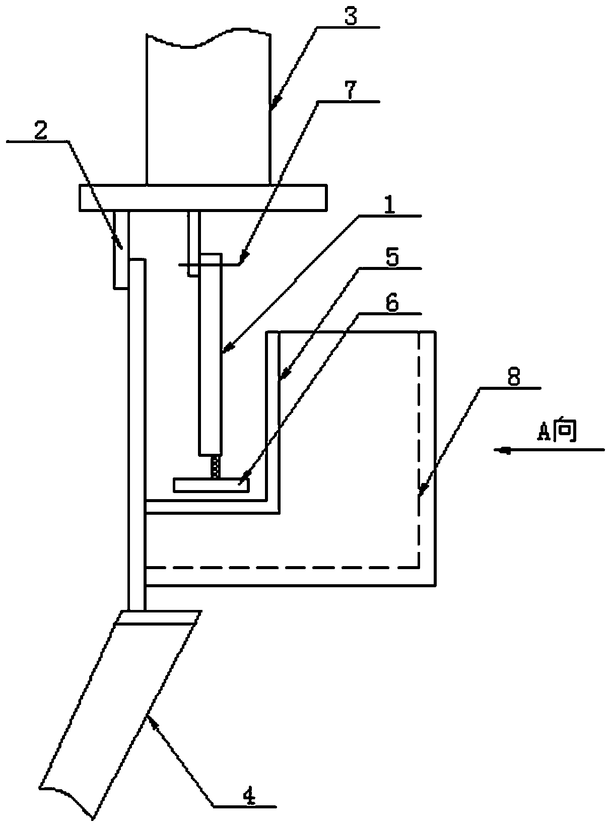
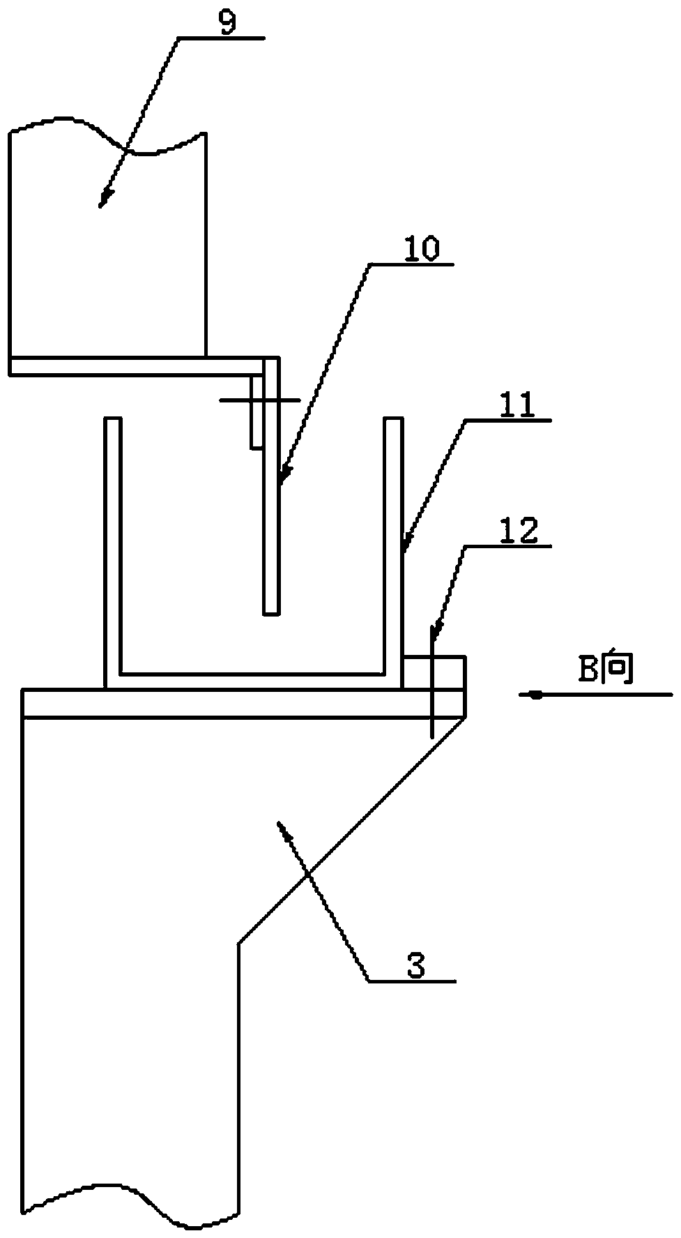
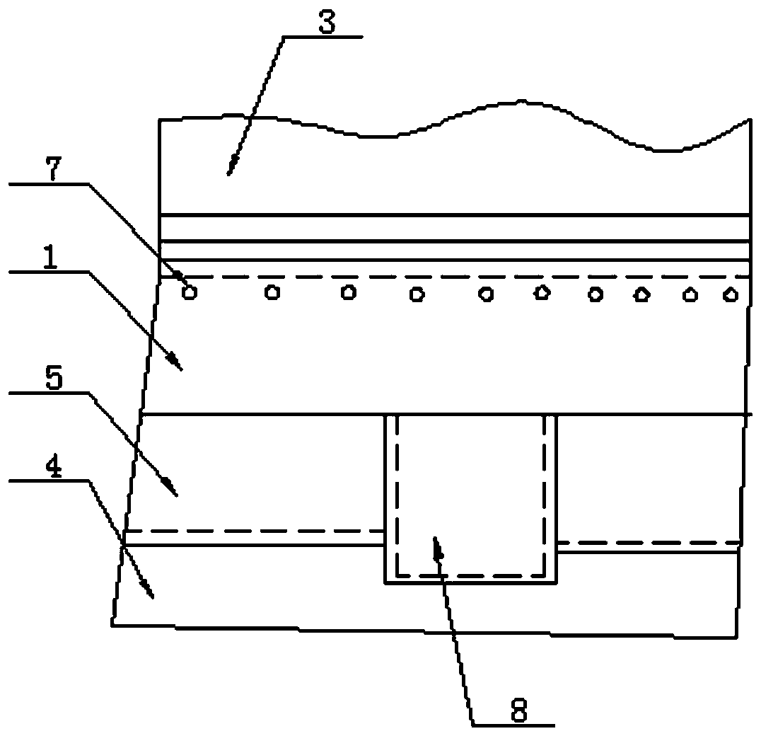
[0020] see as figure 1 —— Figure 4 As shown, this specific embodiment adopts the following technical scheme: it includes an upper seal, a lower seal, a rotary body 3 of an annular cooler, an air box 4 and a heat collecting cover 9 of an annular cooler; the lower seal is arranged on the top of the air box 4 and Between the lower part of the rotary body 3 of the annular cooler, the upper seal is arranged between the upper part of the rotary body 3 of the annul...


PUM


Abstract

The invention discloses a power generation type annular cooler sealing structure, and relates to the technical field of smelting equipment. The upper end of a first wind shield is fixed to the lower portion of an annular cooler rotating body through a first fastener, a plurality of sweepers are fixed to the lower end of the first wind shield, a first water containing mechanism is arranged on the upper portion of an air bellow and is of a U-shaped groove body structure, a groove opening is downward, ash removal grooves are arranged on the two sides of the first water containing mechanism, a dustproof plate is arranged on the inner side of the first water containing mechanism and is in tight fit with the lower portion of the annular cooler rotating body, negative fall is set between the bottoms of the ash removal grooves and the bottom of the first water containing mechanism, a second wind shield is arranged on the lower portion of an annular cooler heat collection cover, a second watercontaining mechanism is fixed to the upper portion of the annular cooler rotating body through a second fastener, and the second wind shield extends downwards to be located in the second water containing mechanism. The time, labor and cost are saved, working environment is comfortable, the problems that the air leakage efficiency is high and operation environment is poor in traditional seal are effectively solved, the power consumption cost of a fan is reduced, and the overhaul work frequency is reduced.

Description

technical field [0001] The invention relates to the technical field of smelting equipment, in particular to a sealing structure of a power generation type annular cooler. Background technique [0002] When sintering in the smelting industry, it is necessary to configure a ring cooler to cool the hot ore. Generally, a blower is used for cooling. The cooling effect depends on the cloth and sealing effect of the ring cooler. If the sealing effect is not good, if the mine cannot cool down, it will have a certain impact on the subsequent processes. Therefore, the speed of the machine must be reduced to ensure the cooling effect. Reducing the speed of the machine will also cause a reduction in production and increase the cost of electricity. The annular cooler for waste heat recovery and power generation directly affects the waste heat power generation and reduces the economic benefits. Moreover, the seal is not good, and the dust and dirt inside the machine leak out from the seal...

Claims


Application Information

Patent Timeline
Patent Type & Authority Applications(China)
IPC IPC(8): F16J15/16F16J15/3284F16J15/40F27D15/02
CPCF16J15/16F16J15/3284F16J15/40F27D15/02
Inventor 宋文军岳嘉森
Owner 唐山瑞泰机械有限公司
Why Eureka
Try Eureka