Eureka AIR delivers breakthrough ideas for toughest innovation challenges, trusted by R&D personnel around the world.

Clutch of a single engine washing and sweeping vehicle and its working method

A technology for clutch and vehicle cleaning, applied in the field of clutches, can solve the problems of the clutch being unable to be engaged at high speed, not being able to be combined at high speed, and the volume of the friction clutch being large.

Active Publication Date: 2019-08-23
厦门仁工环保科技有限公司
View PDF4 Cites 0 Cited by
  • Summary
  • Abstract
  • Description
  • Claims
  • Application Information

AI Technical Summary

Problems solved by technology

[0002] The pneumatic clutches currently used in single-engine sweeping vehicles are either friction clutches or meshing clutches; among them, friction clutches are large in size and small in transmission torque, while meshing clutches are large in transmission torque but cannot be combined at high speed. Two problems: 1) The clutch with high torque cannot be engaged at high speed; 2) The clutch torque that can be engaged at high speed is small

Method used


Image

  • Clutch of a single engine washing and sweeping vehicle and its working method
  • Clutch of a single engine washing and sweeping vehicle and its working method

Examples


Embodiment Construction

[0025] In order to make the above-mentioned features and advantages of the present invention more comprehensible, the following specific embodiments will be described in detail with reference to the accompanying drawings.

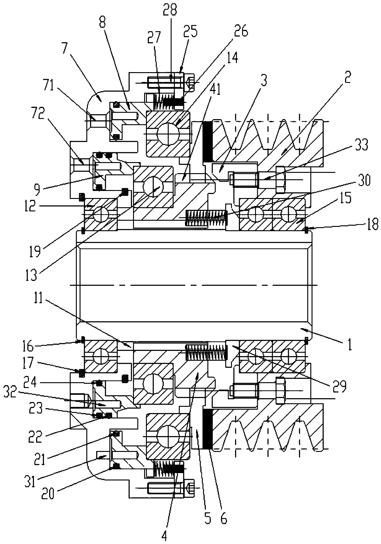
[0026] Such as figure 1 Shown, a kind of clutch of single engine washing and sweeping car, comprises:

[0027] A shaft sleeve 1 for connecting the power input end;

[0028] A pulley 2 is used to connect the power output end; the pulley 2 is rotatably mounted on the outer periphery of the bushing 1, and the rear side of the pulley 2 is provided with an inner ring gear 3;

[0029] A transmission disc 4 is used to transmit the rotational movement of the shaft sleeve 1 to the pulley 2; The shaft sleeve 1 rotates synchronously, and the outer periphery of the front part of the transmission disc 4 is provided with an external tooth 41 capable of engaging and separating from the inner ring gear 3;

[0030] A pressure plate 5 is used to transmit the rotational mo...


PUM


Abstract

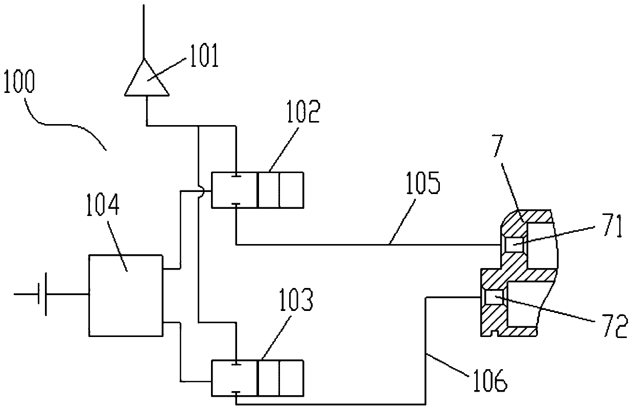
The invention discloses a clutch for a single engine washing and sweeping vehicle and its working method, which comprises a shaft sleeve, a pulley, a transmission plate, a pressure plate and a double-cylinder intake ring, the transmission plate and the pulley are rotatably installed on the outer circumference of the shaft sleeve, and the transmission plate It rotates synchronously with the shaft sleeve, the rear side of the pulley is provided with an inner gear, and the outer periphery of the front part of the transmission disc is provided with external teeth that can be clutched with the inner gear; the pressure plate is installed axially on the outer circumference of the transmission disc, and the pressure plate It rotates synchronously with the transmission plate. The front side of the pressure plate is provided with a friction plate that can be clutched with the rear side of the pulley. The double-cylinder intake ring is provided with a first air intake hole and a first annular cavity connected to the first air intake hole. Body, the second air inlet and the second annular cavity connected with the second air inlet, the first piston is installed in the first annular cavity for pushing the pressure plate close to the pulley, and the second annular cavity is installed in the second annular cavity for pushing The drive plate is close to the second piston of the pulley. The present invention does not limit the engagement speed and can output high torque.

Description

technical field [0001] The invention belongs to the technical field of clutches, and in particular relates to a clutch for a single engine cleaning and sweeping vehicle and a working method thereof. Background technique [0002] The pneumatic clutches currently used in single-engine sweeping vehicles are either friction clutches or meshing clutches; among them, friction clutches are large in size and small in transmission torque, while meshing clutches are large in transmission torque but cannot be combined at high speed. Two problems: 1) the clutch with high torque cannot be engaged at high speed; 2) the clutch torque that can be engaged at high speed is small. Contents of the invention [0003] In order to overcome the defects of the prior art, the technical problem to be solved by the present invention is to provide a single-engine sweeping car clutch and method that does not limit the engagement speed and can output high torque. [0004] In order to solve the above-me...

Claims


Application Information

Patent Timeline
Patent Type & Authority Patents(China)
IPC IPC(8): F16D25/0635F16D25/061F16D25/12
CPCF16D25/061F16D25/0635F16D25/12F16D25/083F16D25/10F16D23/02
Inventor 钟添德钟荣德钟先德
Owner 厦门仁工环保科技有限公司
Why Eureka
Eureka Blog
Learn More