
Robot optimal path forming method for track board point cloud data acquisition

A point cloud data and optimal path technology, applied in the direction of manipulators, program-controlled manipulators, manufacturing tools, etc., can solve problems such as limited measurement points, failure to realize information interaction and collaborative control, and limited layout of photometric measurement points, etc., to achieve Accurately Acquired Effects

Active Publication Date: 2018-08-31
中铁二十二局集团第二工程有限公司 +2
View PDF5 Cites 0 Cited by
  • Summary
  • Abstract
  • Description
  • Claims
  • Application Information

AI Technical Summary

Problems solved by technology

This type of detection method is widely used in engineering, but due to its cumbersome tooling and low detection efficiency, it cannot realize the detection of each track slab, and it is difficult to meet the actual production needs
The second is based on close-range photogrammetry + mechanical drive. This type of method has greatly improved the detection efficiency, but there are still the following shortcomings: the mechanical device that drives the camera movement is relatively complicated, and it cannot achieve flexible data acquisition methods; The photogrammetry method is used to realize the detection of the track slab, the layout of the photogrammetric measurement points is limited, the number of laser beams on the inner surface of the rail support platform is limited, the obtained measurement points are limited, and the fine model of the characteristic parts of the track slab cannot be reconstructed; the scanning equipment and mechanical device The operating systems are independent of each other, and the information interaction and coordinated control of the two cannot be realized; the detection function of a single rail support platform of the track slab is not designed, and timely and efficient retesting work cannot be carried out for the overrun of a single rail support platform

Method used

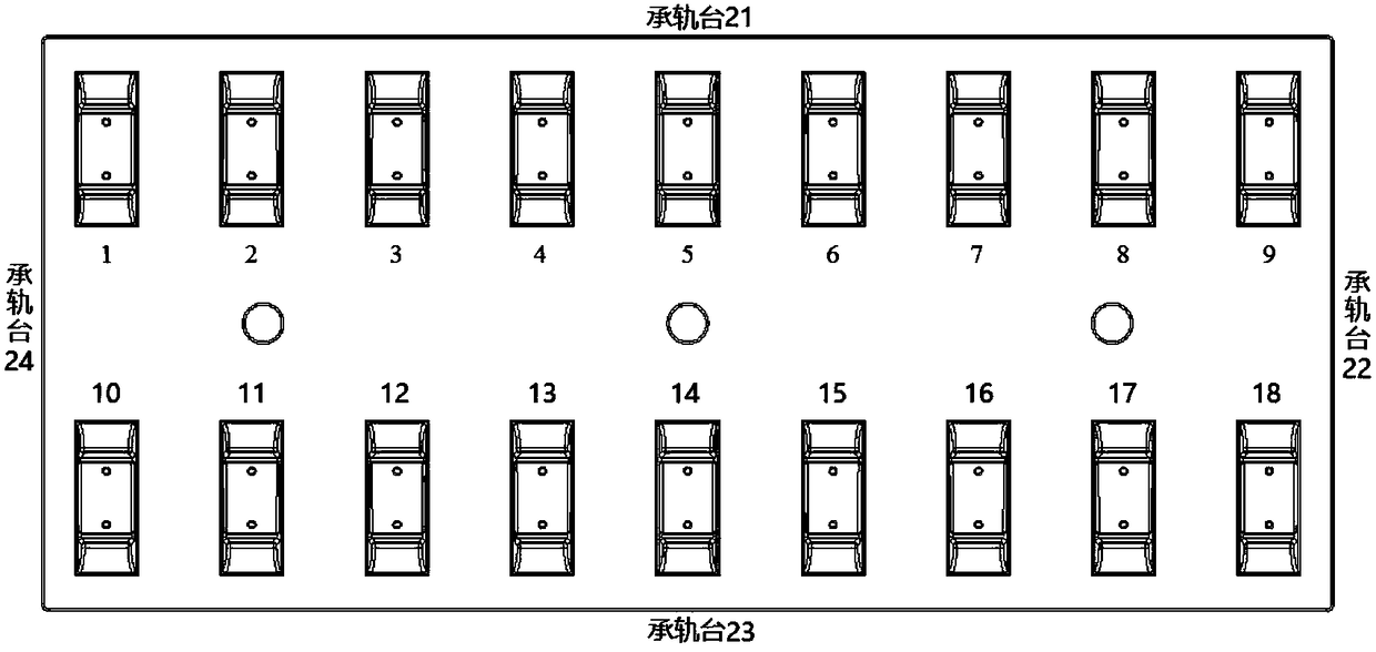
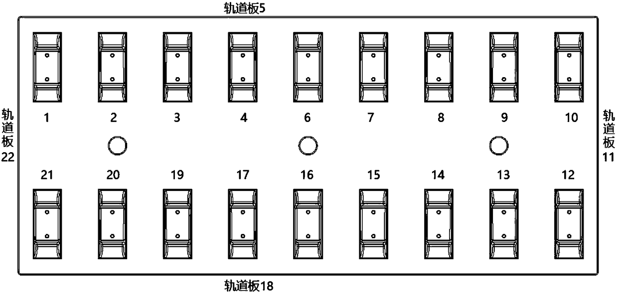

Image

  • Robot optimal path forming method for track board point cloud data acquisition
  • Robot optimal path forming method for track board point cloud data acquisition

Examples


Embodiment Construction

[0029] The implementation of the present invention will be described in detail below in conjunction with the accompanying drawings and examples, so as to fully understand and implement the process of how to apply technical means to solve technical problems and achieve technical effects in the present invention. It should be noted that, as long as there is no conflict, each embodiment and each feature in each embodiment of the present invention can be combined with each other, and the formed technical solutions are all within the protection scope of the present invention.

[0030] In addition, the steps shown in the flow diagrams of the figures may be performed in a computer system, such as a set of computer-executable instructions, and, although a logical order is shown in the flow diagrams, in some cases, the sequence may be different. The steps shown or described are performed in the order herein.

[0031] Specifically, in order to overcome the shortcomings of the prior art,...


PUM


Abstract

The invention discloses a robot optimal path forming method for track board point cloud data acquisition. The method comprises the following steps: step 1) using a photographing scanning method of a three-dimensional imager, obtaining a large number of point cloud data of a surface of a track board and point cloud of feature regions through repeated measurement, the feature regions selecting a middle pouring hole of the track board and peripheral part regions, and middle positions of four side surface of the track board; step 2) programming on a Windows system, to control a Kuka robot to complete automatic motion according to a specific trajectory and process; according to boundary dimensional deviation requirements of the track board, planning a robot motion path, through repeated tests,calculation, and optimization, obtaining an optimal motion path of the robot. The method is fast and efficient, and device operation is safe and stable, and meets a production process, and installation process is simple, and detection results are accurate and reliable.

Description

technical field [0001] The invention relates to the field of high-speed railway track slab detection, in particular to a robot optimal path design method for CRTS III track slab point cloud data collection. Background technique [0002] CRTSⅢ ballastless track slab is a major scientific and technological achievement independently developed by China with completely independent intellectual property rights. Compared with CRTSI and CRTSII track slabs, the detection of CRTSIII track slabs eliminates the need for on-site grinding. The production process is simplified, the cost is reduced, and at the same time, higher requirements are put forward for the precision and quality of the finished board. [0003] At present, there are two main ways to detect the external dimensions of CRTSⅢ ballastless track slabs for high-speed railways: the first one is based on motor-driven total station + special tooling. This type of detection method is widely used in engineering, but due to its c...

Claims


Application Information

Patent Timeline
IPC IPC(8): B25J9/16
CPCB25J9/16B25J9/1664
Inventor 秦飞杜以军吴延江叶昌尧李超杨志国张志伟张献州
Owner 中铁二十二局集团第二工程有限公司
Learn More