
Ultrasonic wave sensor

A sensor and ultrasonic technology, applied in the field of ultrasonic sensors, can solve the problems of high installation height of trucks, achieve the effects of reducing accidents, solving short-distance blind spots, and solving beam angle restrictions

Pending Publication Date: 2018-08-28
清华大学苏州汽车研究院(吴江) +1
View PDF0 Cites 2 Cited by
  • Summary
  • Abstract
  • Description
  • Claims
  • Application Information

AI Technical Summary

Problems solved by technology

[0005] In order to solve the technical problem of the near-distance blind area caused by the high installation height of the truck due to the limitation of the beam angle of the single probe, the invention provides an ultrasonic sensor for the truck, through the combination of multiple probes in the spatial position, two sets of ultrasonic probes Vertically arranged in a straight-down structure to achieve full coverage of the detection range and effectively reduce accidents when trucks are reversing

Method used


Image

  • Ultrasonic wave sensor
  • Ultrasonic wave sensor
  • Ultrasonic wave sensor

Examples


Embodiment

[0021] The preferred embodiments of the present invention will be further described below in conjunction with the accompanying drawings.

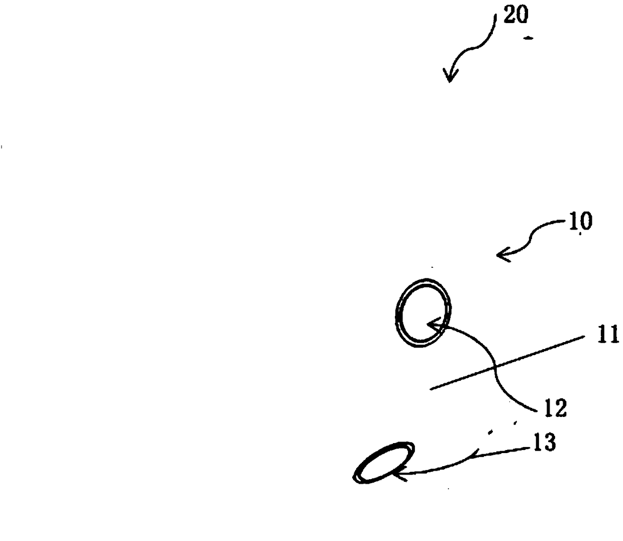
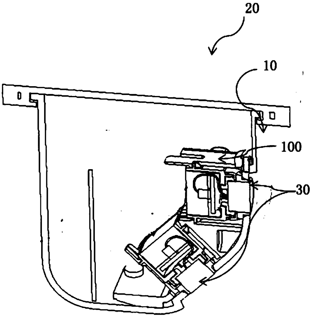
[0022] Such as Figure 1-3 As shown, an ultrasonic sensor of the present invention includes a sensor housing 10, the surface of the sensor housing 10 is provided with a strip-shaped groove 11, and a probe installation port ( 12, 13).

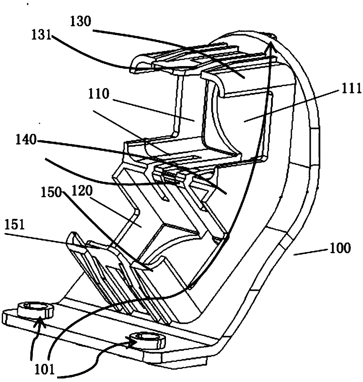
[0023] The sensor housing 10 is provided with a sensor bracket 100 inside. The sensor bracket 100 is used to install the ultrasonic sensor and maintain the relative position between the ultrasonic sensors. The sensor bracket 100 includes a mounting side and a fixed side, and the mounting side is in contact with the sensor housing. The sensor bracket 100 is installed and fixed on the sensor housing 10, for example, can be fixed by screws, and fixing holes 101 can be provided at the upper and lower ends of the sensor bracket 100, and fixed on the sensor housing 10 through the fixing holes 101 by screws.

[00...


PUM


Abstract

The invention discloses a ultrasonic wave sensor. The ultrasonic wave sensor comprises a sensor shell, a sensor support is arranged in the sensor shell, the sensor support comprises a mounting side face and a fixed side face, the mounting side face is in contact with the sensor shell, an upper ultrasonic wave sensor cavity and a lower ultrasonic wave sensor cavity are formed longitudinally on thefixed side face, probe ports are formed in the upper and lower ultrasonic wave sensor cavities, the upper and lower ultrasonic wave sensor cavities are used for mounting ultrasonic wave sensor bodies,the angle between a detection face of the ultrasonic wave sensor body mounted in the upper ultrasonic wave sensor cavity and the ground is 90 degrees, and the angle between the detection face of theultrasonic wave sensor body mounted in the lower ultrasonic wave sensor cavity and the ground is 45 degrees. The ultrasonic wave sensor is used on trucks, through combination of the multiple probes inspaces, the two sets of ultrasonic wave probes are arranged longitudinally to form a straight downward structure, thus full coverage of the detection range is achieved, and the accidents occurring when the trucks back up can be effectively reduced.

Description

technical field [0001] The invention relates to an ultrasonic sensor, in particular to an ultrasonic reversing radar sensor for a truck. Background technique [0002] At present, ultrasonic reversing radar has been widely used in vehicle driving and reversing assistance due to its strong penetrating power, strong reflection ability, simple ranging principle, high ranging accuracy, and low cost. [0003] However, the signal excitation circuit of the current ultrasonic sensor is only connected to one ultrasonic probe, and the distance of the detected object can only be calculated through the time difference between the sending and receiving of ultrasonic waves by the ultrasonic probe, and the coordinate information of the obstacle cannot be obtained; ultrasonic sensors on the market are detected by pairing multiple sensors. Obtain the coordinate information of the obstacle, but if the obstacle is not in the area covered by two adjacent radars, the coordinate information cannot...

Claims


Application Information

Patent Timeline
IPC IPC(8): G01S15/93G01S7/521
CPCG01S7/521G01S15/931
Inventor 吕英超陶煜斌郁宏
Owner 清华大学苏州汽车研究院(吴江)
Learn More