Compressor and air suction silencer thereof

A muffler and compressor technology, which is applied in the direction of machines/engines, mechanical equipment, liquid variable capacity machinery, etc., can solve the problems of poor refrigeration effect and low performance of compressors, so as to reduce temperature, improve energy efficiency ratio, and improve Effect of Gas Transmission Coefficient

Pending Publication Date: 2018-08-28
JIANGSU BAIXUE ELECTRIC APPLIANCES
View PDF1 Cites 0 Cited by
  • Summary
  • Abstract
  • Description
  • Claims
  • Application Information

AI Technical Summary

Problems solved by technology

[0002] In the prior art, for the compressor, when the temperature of the refrigerant coming out of the suction muffler is low, the gas transmission coefficient of the compressor can be increased, thereby improving the energy efficiency ratio (COP) of the compressor. However, when the compressor is working , the mechanical energy is converted into heat energy, the temperature of the compressed cylinder is high, because the suction muffler is in direct heat conduction contact with the compressed cylinder, the heat of the compressed cylinder is transferred to the suction muffler through heat conduction, so the temperature of the refrigerant coming out of the suction muffler is relatively high , so that the performance of the compressor is low and the cooling effect is not good

Method used


Image

  • Compressor and air suction silencer thereof
  • Compressor and air suction silencer thereof
  • Compressor and air suction silencer thereof

Examples


Embodiment Construction

[0026] In order to describe the technical content, structural features, achieved goals and effects of the invention in detail, the following will be described in detail in conjunction with the embodiments and accompanying drawings.

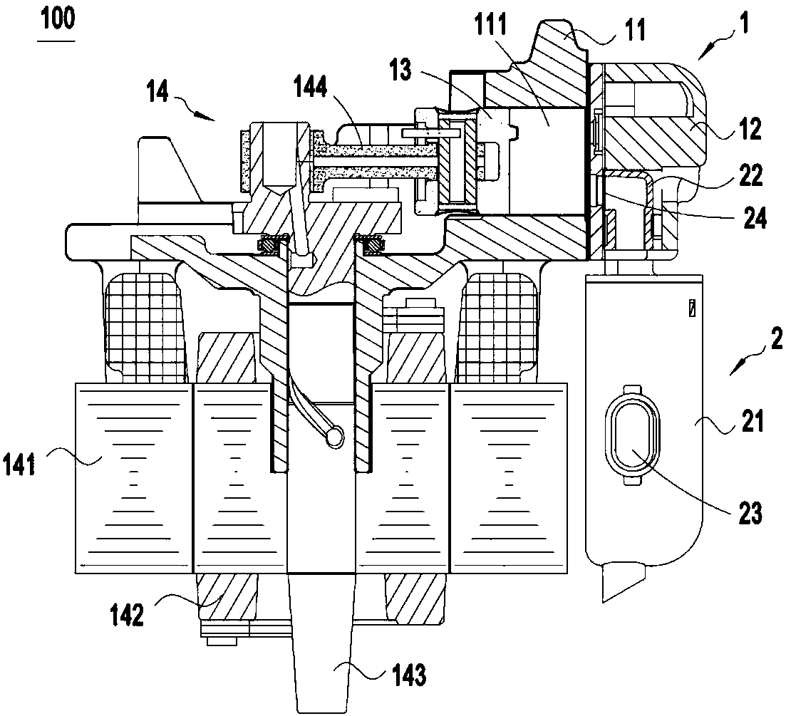
[0027] According to attached figure 1 The compressor 100 shown includes a compression cylinder 11, a cylinder head 12 arranged on the compression cylinder 11, a drive mechanism 13 for driving the compression cylinder 11, and a muffler 2 for delivering refrigerant to the interior of the compression cylinder 11. . A compression chamber 111 is arranged inside the compression cylinder 11, and a piston 13 is arranged in the compression chamber 111. The piston 13 can move back and forth in the compression chamber 111 to carry out compression operations. The driving mechanism 14 includes a stator 141, a rotor 142 arranged in the stator 141, A crankshaft 143 fixedly connected to the rotor 142 , a connecting rod 144 hinged on the crankshaft 143 , and the...


PUM


Abstract

The invention discloses a compressor, belongs to the technical field of refrigeration equipment, and solves the technical problem that in the prior art, direct heat conduction contact between a refrigerant outlet end of an air suction silencer and a compression air cylinder leads to a high temperature of the refrigerant outlet, and as a result, the refrigeration performance of a compressor is nothigh. The compressor comprises a shell, a compression air cylinder, a piston, a driving mechanism and an air suction silencer, wherein a connecting part comprises a joint surface and a refrigerant outlet, the joint surface is used for being combined with an air cylinder cover, the connecting part is provided with at least one heat insulation cavity, and the heat insulation cavities are located onthe periphery of the refrigerant outlet and isolate the refrigerant outlet from the joint surface. Due to the fact that the heat insulation cavities isolate the joint surface for combination of the connecting part and the air cylinder cover from the refrigerant outlet, the heat insulation cavities can obstruct the heat transfer between the refrigerant outlet of the silencer and the air cylinder cover, the temperature of refrigerants entering from the refrigerant outlet to the compression air cylinder can be effectively reduced, the gas transmission coefficient of the compressor is improved, and the coefficient of performance of the compressor is increased.

Description

technical field [0001] The invention relates to the technical field of refrigeration equipment, in particular to a compressor and a suction muffler thereof. Background technique [0002] In the prior art, for the compressor, when the temperature of the refrigerant coming out of the suction muffler is low, the gas transmission coefficient of the compressor can be increased, thereby improving the energy efficiency ratio (COP) of the compressor. However, when the compressor is working , the mechanical energy is converted into heat energy, the temperature of the compressed cylinder is high, because the suction muffler is in direct heat conduction contact with the compressed cylinder, the heat of the compressed cylinder is transferred to the suction muffler through heat conduction, so the temperature of the refrigerant coming out of the suction muffler is relatively high , so that the performance of the compressor is low and the cooling effect is not good. [0003] The Chinese i...

Claims


Application Information

Patent Timeline
IPC IPC(8): F04B39/00F04B39/06
CPCF04B39/0083F04B39/06
Inventor 周正红言伟何静吴其其夏斌
Owner JIANGSU BAIXUE ELECTRIC APPLIANCES
Why Eureka
Try Eureka