
Automatic thread shearing mechanism of sewing machine and sewing machine

A thread trimming mechanism and sewing machine technology, which is applied in the field of sewing machines, can solve the problems of affecting the working efficiency of sewing machines, the waste of sewing threads, and increasing the labor intensity, etc., so as to reduce the area of ​​the operating rotary table, reduce labor costs, and achieve good thread cutting effects Effect

Pending Publication Date: 2018-08-28
本佳安凯(湖南)缝制机械有限公司
View PDF9 Cites 8 Cited by
  • Summary
  • Abstract
  • Description
  • Claims
  • Application Information

AI Technical Summary

Problems solved by technology

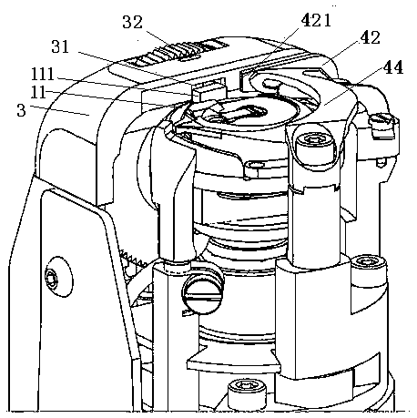
But because of the existence of the positioning groove 31, there is a long distance between the thread trimming position where the fixed knife 42 cooperates with the movable knife 44 and the pinhole 32 on the needle plate, and this distance results in the residue remaining on the sewing material after thread trimming. If the thread end is too long, manual assistance is needed to cut off the excessively long thread end, which affects the working efficiency of the sewing machine, increases the labor intensity, and also causes the waste of sewing thread. There are still defects in the design.

Method used


Image

  • Automatic thread shearing mechanism of sewing machine and sewing machine
  • Automatic thread shearing mechanism of sewing machine and sewing machine
  • Automatic thread shearing mechanism of sewing machine and sewing machine

Examples


Embodiment Construction

[0031] Now, the present invention will be further elaborated in conjunction with specific embodiments and accompanying drawings. However, it should be noted that the structures, proportions, etc. drawn in this embodiment are only used to match the content disclosed in the content of the invention, for those skilled in the art to understand and read, and are not used to limit the conditions that the invention can be implemented , so it has no technical substantive significance. Any adjustments that are the same as or similar to the present invention should fall within the scope of the technical content disclosed in the present invention without affecting the effects and goals that can be achieved by the present invention. within the scope covered. At the same time, for the convenience of description, the present invention uses terms such as "upper", "lower", "left", and "right", but not to limit the applicable scope of the present invention. Substantial changes in technical co...


PUM


Abstract

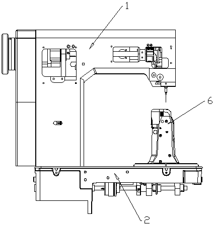
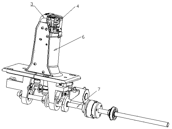
The invention discloses an automatic thread shearing mechanism of a sewing machine and the sewing machine. The thread shearing mechanism comprises a fixed knife holder, a fixed knife, a movable knifeholder and a movable knife; the movable knife rotates to be close to or far away from a pin hole by taking a supporting point, on the movable knife holder, of the movable knife as a fixed point; a thread hooking part used for hooking a thread passing through the pin hole is arranged on the movable knife; the movable knife edge is close to the thread hooking part; a positioning boss protruding fromthe bottom surface of the movable knife is machined at the bottom of the end, far away from the movable knife holder, of the movable knife; correspondingly, a limiting lug is machined on one side ofthe top of the fixed knife holder; the positioning boss and the limiting lug form a limiting space for the protrusion of a rotating shuttle sleeve when the movable knife rotates to the position whichis the most close to the pin hole; and the fixed knife edge, matched with the movable knife edge, in the fixed knife is moved to be close to the pin hole. According to the automatic thread shearing mechanism and the sewing machine, the fixed knife and the movable knife can be conveniently moved to the position close to the pin hole, a thread end left after the thread is sheared can be effectivelyshortened, the phenomenon that excessive thread ends are sheared subsequently and manually can be avoided, the labor intensity can be lowered, and the labor cost can be lowered.

Description

technical field [0001] The invention relates to an automatic sewing machine thread trimming mechanism and a sewing machine, belonging to the technical field of sewing machines. Background technique [0002] Automatic sewing machines are generally provided with a thread trimmer. Thread trimming mechanism in the prior art such as figure 1 As shown, a fixed knife 42 is provided on one side of the needle plate 3, and a movable movable knife 44 is provided to engage with the cutting edge 421 of the fixed knife 42 to cut off the suture. The positioning groove 31 of the rotary hook cover 11 is free to rotate, that is, the protrusion 111 on the rotary hook cover 11 is stuck in the positioning groove 31, thereby realizing the limit of the rotary hook rotary cover 11. But because of the existence of the positioning groove 31, there is a long distance between the thread trimming position where the fixed knife 42 cooperates with the movable knife 44 and the pinhole 32 on the needle pl...

Claims


Application Information

Patent Timeline
Patent Type & Authority Applications(China)
IPC IPC(8): D05B65/00D05B69/02
CPCD05B65/00D05B69/02
Inventor 吴新安吴福安
Owner 本佳安凯(湖南)缝制机械有限公司
Learn More