A six-suspension module medium-speed maglev vehicle running mechanism

A traveling mechanism and maglev technology, applied in vehicle components, electric vehicles, electric traction, etc., can solve the problems of reducing train-rail coupling vibration, insufficient effective carrying capacity, and failing to reach the medium speed range, so as to reduce the train-rail coupling. Vibration, convenient for daily use and maintenance, and the effect of improving suspension stability

Active Publication Date: 2019-11-01
SOUTHWEST JIAOTONG UNIV
View PDF1 Cites 0 Cited by
  • Summary
  • Abstract
  • Description
  • Claims
  • Application Information

AI Technical Summary

Problems solved by technology

[0003] Among the existing design schemes of medium and low-speed maglev trains, ten power units with five suspension modules or six power units with three suspension modules are more typical. The maximum applicable speed does not exceed 120km / h, which can only be applied to urban rail transit in the city
Moreover, the design of the running mechanism is relatively complicated, the dynamic effect of the suspension module and the line is significant, and the effective carrying capacity is insufficient, which restricts its application in urban rail transit
[0004] Through the above analysis, it is believed that there are certain deficiencies in the running mechanism of the existing medium and low-speed maglev vehicles, which are worthy of improvement. The main performances are as follows: first, the applicable speed of the running mechanism is not enough, it cannot reach the medium speed range, and it cannot expand its applicable market; The optimal design of the structure was not considered in the case of the limited suspension capacity of the running mechanism itself. The structure is relatively complex, which causes inconvenience to daily use and maintenance, and the lightweight design is insufficient. The effect is obvious, which is not conducive to reducing the coupling vibration of train rails

Method used


Image

  • A six-suspension module medium-speed maglev vehicle running mechanism
  • A six-suspension module medium-speed maglev vehicle running mechanism
  • A six-suspension module medium-speed maglev vehicle running mechanism

Examples


Embodiment Construction

[0018] In order to facilitate those skilled in the art to understand the technical content of the present invention, the content of the present invention will be further explained below in conjunction with the accompanying drawings.

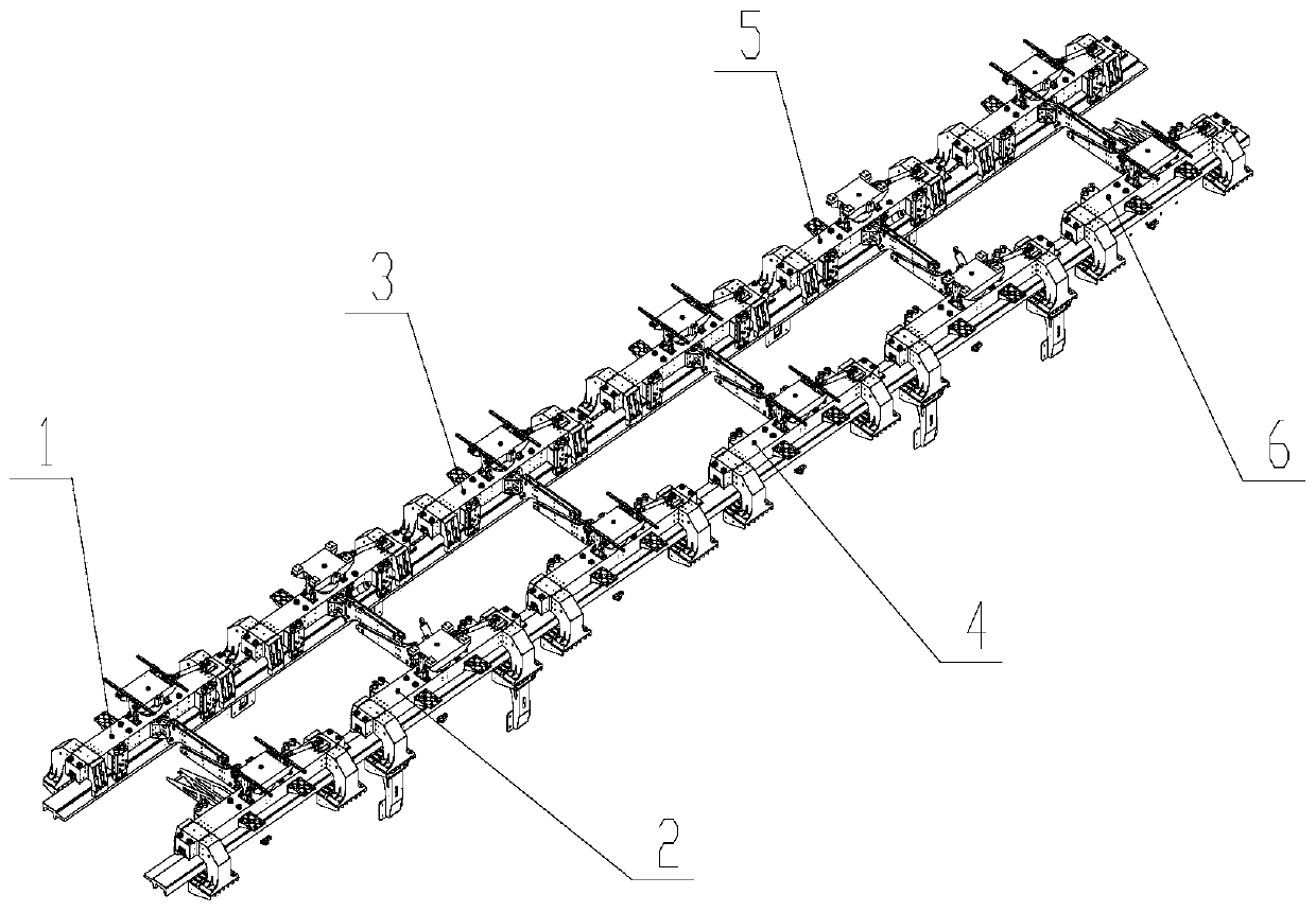
[0019] A six-suspension-module medium-speed maglev vehicle running mechanism of the present invention adds a suspension module to the existing five-suspension-module medium-speed maglev vehicle running mechanism, and cancels the forced guide mechanism, so the suspension and With excellent traction performance, compact and reasonable structure, and low power interaction with the line, it can meet the needs of medium-speed applications with a speed of not less than 180km / h.

[0020] Such as figure 1 As shown, the present invention includes six suspension modules arranged longitudinally along the vehicle body; they are sequentially recorded as: the first suspension module 1, the second suspension module 2, the third suspension module 3, the fourth s...


PUM


Abstract

The invention discloses a middle-speed magnetic levitation vehicle walking mechanism with six suspension modules. On the basis of an existing middle-speed magnetic levitation vehicle walking mechanismwith five suspension modules, another suspension module is added, and therefore the running speed of a maglev train can be increased to a high and middle speed range. The maximum applicable speed ofthe walking mechanism is not lower than 180 km / h, and the application market of current middle-low speed maglev trains is expanded. Each suspended rack adopts a pair of bag-type large air springs distributed on the left and right sides of the middle part of the suspended rack, the dynamic effect between the suspended racks and a circuit is small, the coupling vibration of train tracks can be remarkably reduced, and the suspension stability of the maglev trains is improved. Optimal design is conducted on power units, suspension units and the suspended racks of the suspension modules, the walking mechanism is simplified, and more convenience is provided for daily use and maintenance.

Description

technical field [0001] The invention belongs to the field of running mechanisms of maglev vehicles, in particular to a running mechanism of medium-speed maglev vehicles. Background technique [0002] The medium and low-speed maglev train adopts EMS electromagnetic attraction suspension and linear motor traction. Compared with traditional wheel-rail rail transit, it has the advantages of safety, economy, high comfort, strong ability to pass through ultra-small curves, and strong climbing ability. A new type of urban passenger rail transit system with good development prospects. [0003] Among the existing design schemes of medium and low-speed maglev trains, ten power units with five suspension modules or six power units with three suspension modules are more typical. The maximum applicable speed does not exceed 120km / h, which can only be applied to urban rail transit in the city . Moreover, the design of the running mechanism is relatively complicated, the dynamic effect o...

Claims


Application Information

Patent Timeline
Patent Type & Authority Patents(China)
IPC IPC(8): B60L13/04
CPCB60L13/04
Inventor 马卫华胡俊雄胡齐斌罗世辉
Owner SOUTHWEST JIAOTONG UNIV
Why Eureka
Try Eureka