
Winding machine

A winding machine and winding technology, applied in the field of machinery, can solve the problems of limiting the number of turns of nylon wire winding, uneven distribution of nylon wire, low winding quality, etc. Effect

Pending Publication Date: 2018-08-28
淮安超跃橡塑有限公司
View PDF8 Cites 0 Cited by
  • Summary
  • Abstract
  • Description
  • Claims
  • Application Information

AI Technical Summary

Problems solved by technology

[0003] The invention provides a winding machine, which solves the problem that the winding device of the winding machine in the prior art winds the nylon wire at a certain height, resulting in uneven distribution of the nylon wire, resulting in low winding quality and limiting the number of winding turns of the nylon wire.

Method used


Image

  • Winding machine
  • Winding machine
  • Winding machine

Examples


Embodiment Construction

[0031] The present invention will be further described below in conjunction with the accompanying drawings and embodiments.

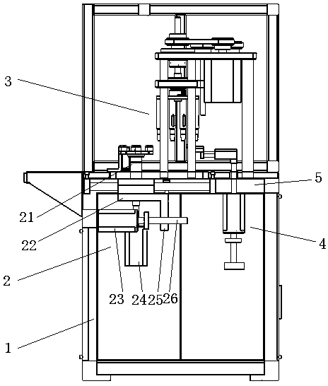
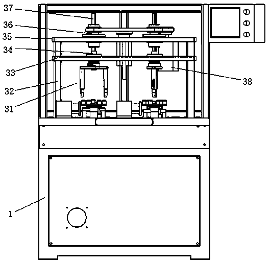
[0032] Such as figure 1 , figure 2 , image 3 , Figure 4 , Figure 5 , Figure 6 , Figure 7 , Figure 8 , Figure 9 as well as Figure 10As shown, a winding machine includes a machine platform 1, a magnetic tensioner arranged on the top of the machine platform 1, a support plate 5 arranged in the middle of the machine platform 1, a sliding table assembly 2, a floating winding assembly 3 up and down, and a wire height Control assembly 4, the slide table assembly 2 includes a slide table 22 slidably connected to the support plate 5 and a plurality of pre-fixed device shafts 21 rotatably connected to the slide table 22, between the slide table 22 and the machine table 1 A push-pull device is provided; the up and down floating winding assembly 3 includes a plurality of winding pillars 32 arranged on the support plate 5, a winding fixing plate 35...


PUM


Abstract

The invention discloses a winding machine. The winding machine comprises a machine board, magnetic tension devices arranged at the top of the machine board, a supporting plate arranged in the middle of the machine board, a sliding table assembly, an up-down floating winding assembly and a thread height control assembly. The winding machine is simple in structure; winding rotating shafts drive winding rods to move from bottom to top, so that nylon threads are uniformly distributed, and the winding quality of a connecting plate is ensured; in addition, the nylon threads are uniformly distributed, so that the circle number of the nylon threads can be improved to a certain degree; a lifting motor controls the height of thread outlet planes by a lead screw; in addition, an air cylinder pushes acorresponding height control board to beside of the buffer connecting plate; when the winding rods wind, the nylon threads first get in contact with guide inclined planes, then pass through the thread outlet planes and wind two adjacent hollow driving shaft connecting plates, that is, the nylon threads leave from the thread outlet planes and immediately wind the two adjacent hollow driving shaftconnecting plates; with short distance, deviation of the nylon threads is avoided, and thereby the lifting motor well ensures the height of the nylon threads by the thread outlet planes, and the uniformity of the nylon threads is further improved; the application range of the winding assembly is wider.

Description

technical field [0001] The invention relates to the field of machinery, in particular to a winding machine. Background technique [0002] The buffer connection plate is used as the connecting part of the automobile transmission shaft, and its performance is directly related to the overall performance of the vehicle. The wear of the transmission shaft, the connection disc is usually made of several independent hollow transmission shaft connection discs wound by nylon fiber winding, and several independent hollow transmission shaft connection discs are usually fixed on the pre-fixed device during the production process (this On 2014-04-29, the applicant applied for a patent titled "A Pre-fixing Device for Automobile Buffering Coil Winding Group", the patent number is "201420212362.2"), and then a certain nylon wire was wound by the winding machine, and the winding wire The winding device of the machine winds the nylon wire at one height, and the uneven distribution of the nyl...

Claims


Application Information

Patent Timeline
Patent Type & Authority Applications(China)
IPC IPC(8): B29C53/56B29C53/80
CPCB29C53/564B29C53/8008B29C53/8016B29C53/8091B29L2031/7728Y02P70/50
Inventor 李高亮孙军
Owner 淮安超跃橡塑有限公司
Learn More