A large-stroke press-in mechanism for micro-nano scribing

A technology with a large stroke and enlarged mechanism, which is applied in the field of probe-based micro-nano scribing, can solve the problems of poor dynamic performance of the press-in mechanism, limited processing speed, and small stiffness of the cantilever beam, so as to compensate for coupling errors and enhance stability. , the effect of improving stability

Inactive Publication Date: 2020-01-07
TIANJIN UNIV
View PDF7 Cites 0 Cited by
  • Summary
  • Abstract
  • Description
  • Claims
  • Application Information

AI Technical Summary

Problems solved by technology

[0002] With the continuous development of science and technology such as biomedicine and semiconductors, higher requirements are placed on devices and equipment with more functions and smaller sizes. The existing micro-nano processing methods have problems that cannot be solved by themselves, such as The photolithography processing method is expensive, and the nanoimprint technology can only process the same structure as the master pattern, while the micro-nano scribing technology based on the probe has the characteristics of low cost, simple control, and can process patterns of any shape. A micro-nano processing technology with broad application prospects
However, in the traditional probe processing method based on atomic force microscope, due to the small stiffness of the cantilever beam connecting the driving mechanism and the probe, the dynamic performance of the entire press-in mechanism is poor, resulting in limited processing speed, and for the processing of superhard materials There are great restrictions, and due to the great difference in the stiffness of the cantilever beam in the forward and lateral directions, the machining direction has a great influence on the machining effect

Method used


Image

  • A large-stroke press-in mechanism for micro-nano scribing
  • A large-stroke press-in mechanism for micro-nano scribing

Examples


Embodiment Construction

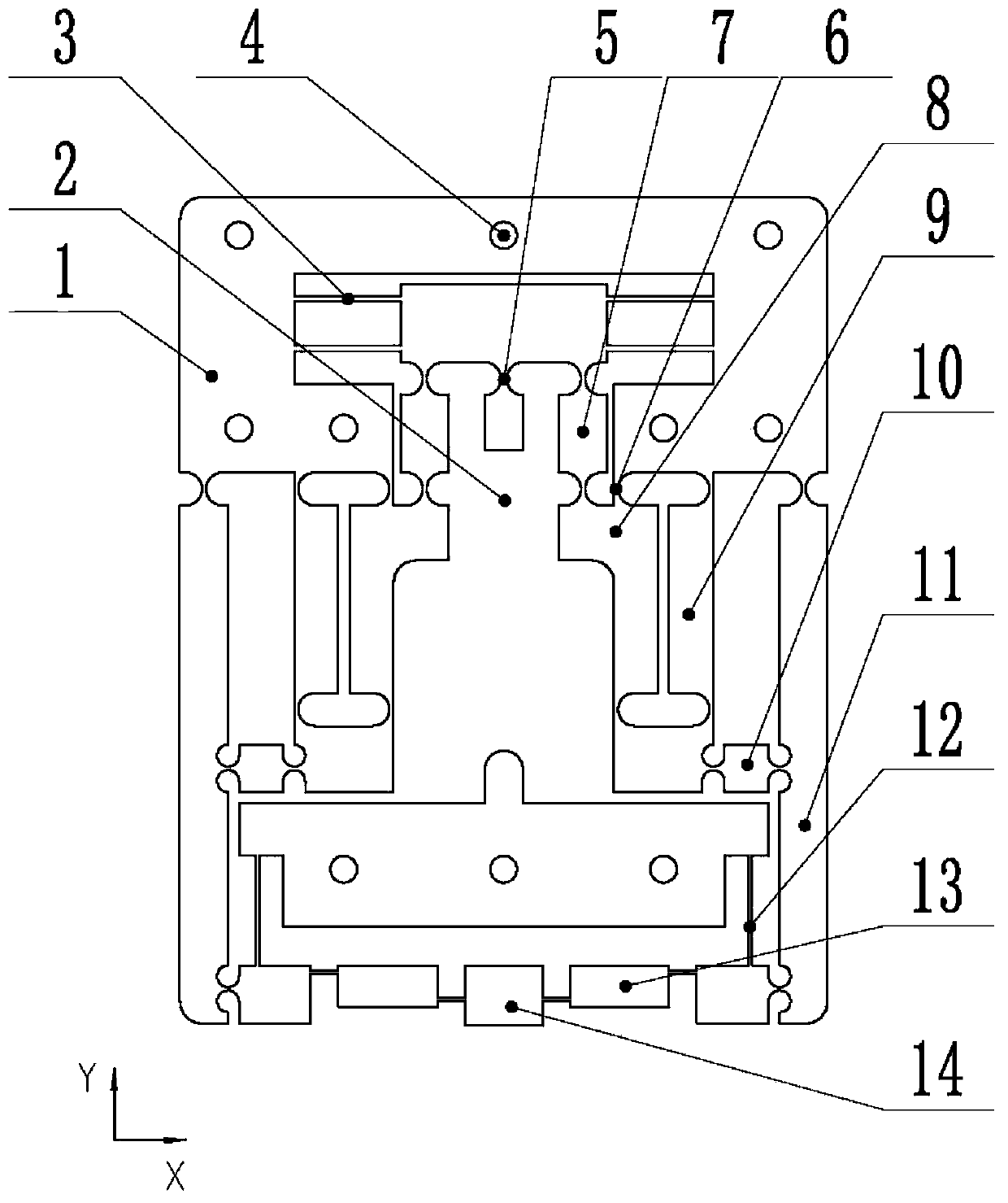
[0017] In order to further understand the invention content, characteristics and effects of the present invention, the following examples are given, and detailed descriptions are as follows in conjunction with the accompanying drawings:

[0018] see Figure 1 ~ Figure 2 , which is a high-precision, high-stability large-stroke press-in mechanism for micro-nano scribing in this embodiment. 5 is connected with the double parallel plate guide mechanism 3, the double parallel plate guide mechanism 3 is connected with the lever amplification mechanism I8 through the connecting rod I7, and then connected with the parallelogram guide mechanism 9 through the semi-notch type flexible hinge 6, wherein the parallelogram guide mechanism 9 Share a rod with the lever amplification mechanism I 8, the parallelogram guide mechanism 9 is connected with the lever amplification mechanism II 11 through the connecting rod II 10, and directly connected with the bridge type amplification mechanism 13 ...


PUM


Abstract

The invention discloses a large-stroke press-in mechanism for micro-nano carving. The large-stroke press-in mechanism comprises a probe installing platform. A left-right symmetry form is adopted in the press-in mechanism, and a base body, a piezoelectric ceramic driver, a lever amplification mechanism I, a double parallel plate guiding mechanism, a parallelogram guiding mechanism, a lever amplification mechanism II, a flexible supporting mechanism and a bridge type amplification mechanism are included. The piezoelectric ceramic driver is arranged at the center position of the press-in mechanism and connected with the double parallel plate guiding mechanism through a notch type flexible hinge. The double parallel plate guiding mechanism is connected with the lever amplification mechanism Ithrough a connecting rod I. The lever amplification mechanism I is connected with the parallelogram guiding mechanism through a half notch type flexible hinge. The parallelogram guiding mechanism is connected with the lever amplification mechanism II through a connecting rod II and connected with the bridge type amplification mechanism through the flexible supporting mechanism. The bridge type amplification mechanism is connected to the probe installing platform. The large-stroke press-in mechanism has the beneficial effects of being high in precision, high in stability and large in stroke.

Description

technical field [0001] The invention relates to the technical field of probe-based micro-nano scribing, in particular to a large-stroke press-in mechanism for micro-nano scribing. Background technique [0002] With the continuous development of science and technology such as biomedicine and semiconductors, higher requirements are placed on devices and equipment with more functions and smaller sizes. The existing micro-nano processing methods have problems that cannot be solved by themselves, such as The photolithography processing method is expensive, and the nanoimprint technology can only process the same structure as the master pattern, while the micro-nano scribing technology based on the probe has the characteristics of low cost, simple control, and can process patterns of any shape. A micro-nano-fabrication technology with broad application prospects. However, in the traditional probe processing method based on atomic force microscope, due to the small stiffness of th...

Claims


Application Information

Patent Timeline
Patent Type & Authority Patents(China)
IPC IPC(8): B23P19/02
CPCB23P19/02
Inventor 田延岭卢康康王福军张大卫
Owner TIANJIN UNIV
Why Eureka
Try Eureka