
Unmanned aerial vehicle real-time tension detection device and tension detection method thereof

A tensile force detection and unmanned aerial vehicle technology, which is applied to measuring devices, force/torque/power measuring instruments, instruments, etc., can solve the problems of easy vibration of the nose structure, small rigidity of the section, and low structural strength, etc., and achieve accurate real-time Tensile test method, few moving parts, reasonable structure effect

Pending Publication Date: 2018-08-24
陈俊胤
View PDF12 Cites 4 Cited by
  • Summary
  • Abstract
  • Description
  • Claims
  • Application Information

AI Technical Summary

Problems solved by technology

[0008] During the manufacturing and testing process, the applicant found that the linear guide rail-type dynamic tension detection solution can achieve a certain anti-torsion function and limit the propeller and motor to move only along the axial direction of the fuselage. However, the design of multiple guide rails, The structural strength is not high. Due to the small cross-section of a single rod and insufficient rigidity, during the actual test process, as the speed of the propeller increases, the nose structure is prone to shake. This is caused by the inherent limitations of the linear guide rail force measurement scheme. of

Method used


Image

  • Unmanned aerial vehicle real-time tension detection device and tension detection method thereof
  • Unmanned aerial vehicle real-time tension detection device and tension detection method thereof
  • Unmanned aerial vehicle real-time tension detection device and tension detection method thereof

Examples


Embodiment Construction

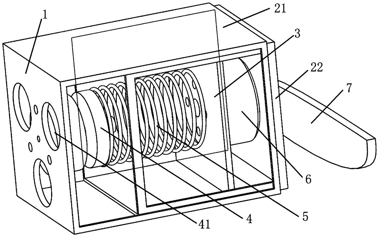
[0052] like figure 1 As shown, the UAV real-time tension detection device of the present invention includes a mounting base 1, a first fixed sleeve 21, a second fixed sleeve 22, a motor mount 3, a tension sensor 4, a spring 5, a motor 6, and a paddle 7 , attitude sensor 41;

[0053] The installation base 1 is fixed on the fuselage, and the tension sensor 4 is fixed on the installation base 1;

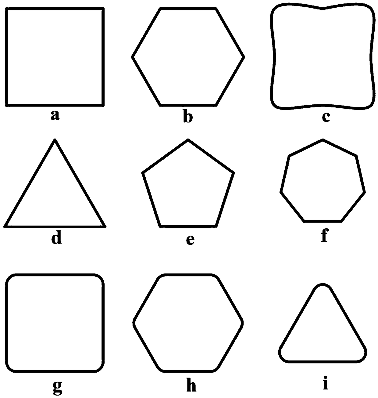
[0054] figure 2 An enlarged view of the installation base 1 in the specific embodiment is given;

[0055] The first fixing sleeve 21 is fixed on the fuselage;

[0056] The paddle 7 is connected with the motor shaft directly or through an intermediate gear transmission;

[0057] The motor is mounted on the motor mount 3, and the motor mount 3 is mounted on the second fixed sleeve 22;

[0058] The second fixing sleeve 22 is embedded or embedded in the first fixing sleeve 21. During actual operation, the two can slide relative to each other. The first fixing sleeve 21 and the second ...


PUM

PropertyMeasurementUnit
Stiffness coefficientaaaaaaaaaa
Wall thicknessaaaaaaaaaa

Abstract

The invention discloses an unmanned aerial vehicle real-time tension detection device and a detection method thereof, and belongs to the technical field of force measurement. The unmanned aerial vehicle real-time tension detection device comprises a first fixed sleeve, a second fixed sleeve, an installing base, a motor fixing seat, a tension sensor, a motor, a vibration reduction spring and a propeller, wherein the motor and the propeller are fixed on the motor fixing seat; the first fixing sleeve is connected with a machine body; the second fixing sleeve is internally sleeved or externally sleeved onto the first fixing sleeve and is provided with a position limiting device in the axial direction; the motor fixing seat and the second fixing sleeve are in rigid connection; meanwhile, the motor fixing seat is connected with one end of the tension sensor through the vibration reduction spring; the other end of the tension sensor is fixed on the installing base; the installing base is fixed onto the machine body. The non-circular sleeve type design is used, so that the reverse twisting force generated when the motor and the propeller work can be counteracted; the free movement can be performed in the tension direction; the tension detection function is realized.

Description

technical field [0001] The invention relates to the technical field of force measurement, in particular to a real-time tension detection device and a tension detection method for an unmanned aerial vehicle. Background technique [0002] The air propeller is the main propulsion method of the UAV, and its efficiency under working conditions directly affects the efficiency of the UAV power system, thus affecting the endurance time of the UAV. [0003] The traditional propeller tension measuring device is to directly connect the motor and the propeller part with the load cell. Typical patents using this kind of scheme include [CN201420711412-propeller motor tension testing device], [CN201620555138-a drone Powertrain Test Platform]. The disadvantage of this type of solution is that system vibration will inevitably occur during the rotation of the propeller. Since the power part and the force measuring part are rigidly connected once, the high-frequency vibration is directly tra...

Claims


Application Information

Patent Timeline
IPC IPC(8): G01L5/00
CPCG01L5/00
Inventor 陈俊胤
Owner 陈俊胤
Learn More