
Gantry crane and steering method thereof

A gantry crane and flange technology, applied in the field of machinery, can solve the problems of difficult steering of gantry cranes

Active Publication Date: 2019-11-19
BEIJING INST OF ENVIRONMENTAL FEATURES
View PDF4 Cites 0 Cited by
  • Summary
  • Abstract
  • Description
  • Claims
  • Application Information

AI Technical Summary

Problems solved by technology

[0004] The technical problem to be solved by the present invention is that it is difficult for the gantry crane to turn in a narrow area. Aiming at the defects in the prior art, a technical solution is provided to solve the difficulty in turning the gantry crane in a narrow area

Method used


Image

  • Gantry crane and steering method thereof
  • Gantry crane and steering method thereof
  • Gantry crane and steering method thereof

Examples


Embodiment 1

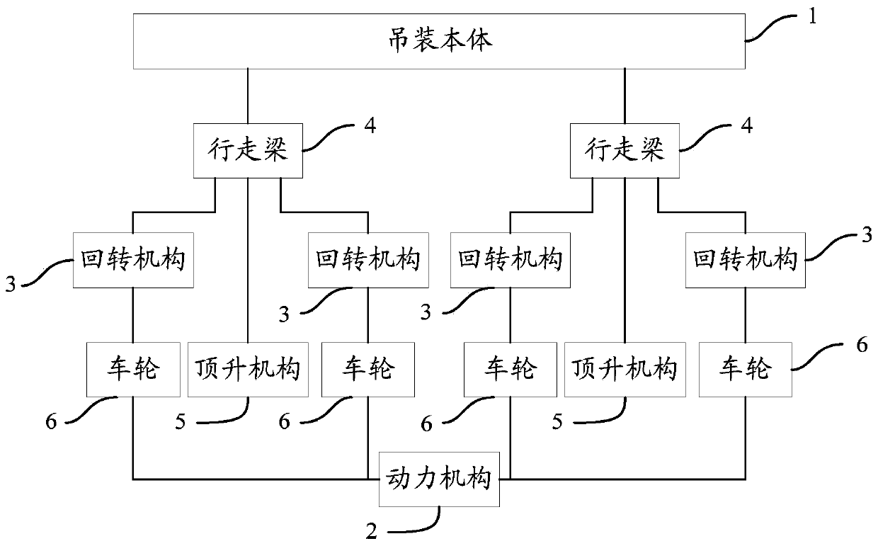
[0076] Such as figure 1 As shown, the gantry crane includes a door-shaped hoisting body 1, and also includes a power mechanism 2, four slewing mechanisms 3, two walking beams 4, two jacking mechanisms 5 and four wheels 6; Beams 4 are respectively arranged on the lower ends of the two supporting columns of the door-shaped hoisting body 1; in the middle part of the walking beam 4 and below the walking beam 4, a jacking mechanism 5 is arranged; Below the walking beam 4, one said slewing mechanism 3 is respectively arranged on both sides of said jacking mechanism 5; four said wheels 6 are mounted on four said slewing mechanisms 3 one by one; said jacking mechanism 5. It is used to jack up a correspondingly connected current walking beam 4 so that the two wheels 6 connected to the current walking beam 4 through the slewing mechanism 3 are out of contact with the ground; The current walking beam 4 is lowered so that the two wheels 6 connected to the current walking beam 4 through t...

Embodiment 2

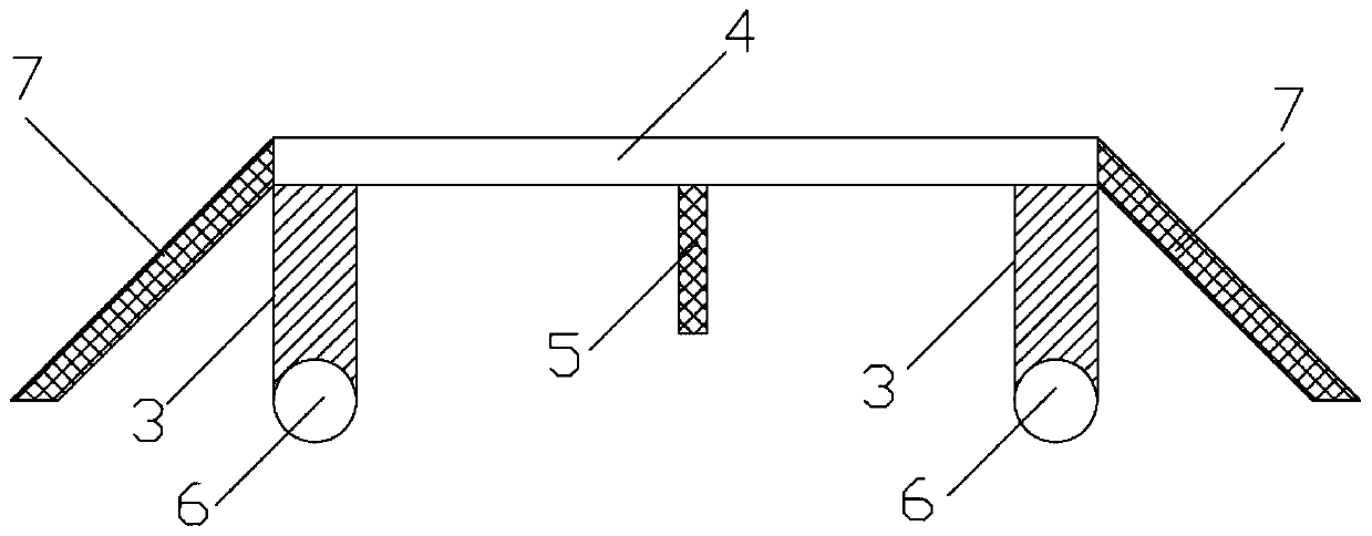
[0080] Please refer to figure 2 , the second embodiment is basically the same as the first embodiment, the similarities will not be repeated, the difference is that: the walking beam 4 is parallel to the width direction of the hoisting body 1; the gantry crane also includes: four auxiliary supports arm 7; wherein, the two ends of the walking beam 4 are respectively connected to the first end of one of the auxiliary support arms 7; the second ends of the four auxiliary support arms 7 can be distributed in a rectangular shape, and the present The length of the rectangle is the same as the distance between the two walking beams 4 , and the width of the rectangle presented is larger than the width of the hoisting body.

[0081] In the second embodiment, since the gantry crane has a large external dimension, but its width is relatively small relative to its length and height, an auxiliary support arm is provided at the two ends of the walking beam respectively, and the auxiliary s...

Embodiment 3

[0083] Please refer to figure 2 , this third embodiment can be realized based on the foregoing embodiments, and in this third embodiment, the auxiliary support arm 7 is detachably connected to the end of the walking beam 4 .

[0084] In the third embodiment, the auxiliary support arm is detachably connected to the end of the walking beam. When the gantry crane runs and turns in a narrower area, the auxiliary support arm can be disassembled to reduce the width of the gantry crane, so as to meet the needs of the gantry crane in a more narrow area. Space requirements for operation and steering in narrow areas.


PUM


Abstract

The invention relates to a portal crane and a steering method thereof. The portal crane comprises a hoisting body, and further comprises a power mechanism, four rotary mechanisms, two traveling beams,two jacking mechanisms and four wheels. The two traveling beams are arranged at the lower end of the hoisting body. Each jacking mechanism is arranged in the middle of the corresponding traveling beam and located below the traveling beam. The two rotary mechanisms are arranged below the corresponding traveling beam and located on the two sides of each jacking mechanism correspondingly. The four wheels are mounted on the four rotary mechanisms correspondingly. Each jacking mechanism can jack up or lower the traveling beam connected with the jacking mechanism. The advancing direction of the wheels mounted on the corresponding rotary mechanisms can be adjusted through the rotary mechanisms. The power mechanism is used for driving the wheels connected with the target traveling beam to advancein the advancing direction of the wheels through the corresponding rotary mechanisms when at least one target traveling beam is not jacked up by the corresponding jacking mechanism. The portal craneprovided by the embodiment of the invention can implement steering in a narrow region.

Description

technical field [0001] The invention relates to the technical field of machinery, in particular to a gantry crane and a steering method thereof. Background technique [0002] At present, in order to facilitate the movement of the gantry crane from the parking area to the working area, the gantry crane usually consists of a door-shaped hoisting body and a tire-type walking mechanism that supports the hoisting body. Line walking, in order to realize the steering of the gantry crane. The overall size of the gantry crane is relatively large. When the tire-type traveling mechanism travels in an arc to realize the steering of the gantry crane, the steering radius is relatively large. When the working area is relatively narrow, it is difficult to realize the steering of the gantry crane. [0003] Therefore, in view of the above deficiencies, it is necessary to provide a technical solution to solve the difficulty of turning the gantry crane in a narrow area. Contents of the inven...

Claims


Application Information

Patent Timeline
Patent Type & Authority Patents(China)
IPC IPC(8): B66C5/02B66C13/00
CPCB66C5/02B66C13/00
Inventor 孙新学韩志忠万喆武自卫
Owner BEIJING INST OF ENVIRONMENTAL FEATURES
Learn More