
Automatic cable winding device

A winding device and cable technology, applied in the directions of transportation and packaging, transportation of filamentous materials, and thin material processing, can solve the problems of high labor intensity, degumming of cables, uneven winding of cables, etc. The effect of product quality, labor intensity reduction, and ease of use

Pending Publication Date: 2018-08-24
广西和联胜电缆有限公司
View PDF8 Cites 5 Cited by
  • Summary
  • Abstract
  • Description
  • Claims
  • Application Information

AI Technical Summary

Problems solved by technology

The traditional winding method is to manually use a cylindrical rod to wind the cable around the cylindrical rod to form a cylindrical reel. This method is labor-intensive and low in production efficiency. Therefore, with the market needs, some winding devices have appeared at present, which place the cylindrical rod on the workbench, and then drive the cylindrical rod to rotate through the motor, so as to realize automatic winding. However, this type of winding device is very simple and can only replace manual labor. Rewinding, using this type of rewinding device to rewind the cables is prone to uneven rewinding and unevenness of each layer of cables, resulting in the problem of friction between the cables and degumming, and, after rewinding The cables still need to be removed from the workbench manually, the labor intensity is still very high, and the operation safety is not guaranteed at the same time

Method used


Image

  • Automatic cable winding device
  • Automatic cable winding device

Examples


Embodiment Construction

[0020] The present invention will be further described below in conjunction with the specific embodiments in the accompanying drawings.

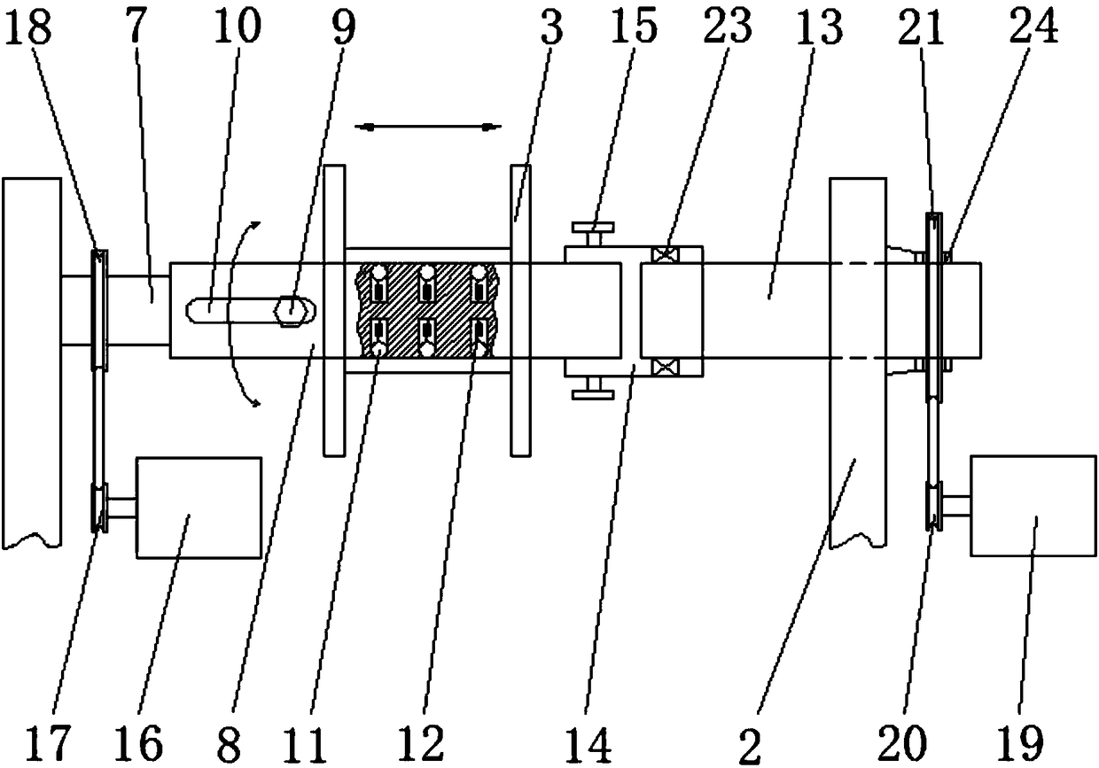
[0021] refer to Figure 1-2 , an automatic cable winding device of the present invention, comprising a base 1 and a support frame 2, wherein both the base 1 and the support frame 2 are frame-type structures, and the middle parts of the two are hingedly connected so that the two can be relatively Turn, one end of the support frame 2 is provided with a reel 3 for rewinding the cable, and the other end is provided with a lifting assembly for lifting the reel 3. When a roll of cable is full, the lifting assembly can be operated to move the cable The coil is lowered to the ground or on a trolley without manual movement. A retractable support assembly for installing the reel 3 is provided on the support frame 2, and a pullable coil is provided on the support frame 2 on the opposite side of the support assembly. The transmission mechanism of the l...


PUM


Abstract

The invention discloses an automatic cable winding device. The automatic cable winding device comprises a base and a support frame; the base is hinged with the middle part of the support frame; a winding drum for winding cables is arranged at one end of the support frame; a lifting module for lifting the winding drum is arranged at the other end of the support frame; the support frame is providedwith a support module used for mounting the winding drum and capable of extending; and the support frame on the opposite side to the support module is provided with a transmission mechanism capable ofpulling the winding drum to displace left and right. The automatic cable winding device further comprises a first driving device for driving the support module to rotate so as to drive the winding drum to rotate, and a second driving device for driving the transmission mechanism to move to drive the winding drum to displace. The automatic cable winding device is compact in structure and convenient to use, can tidily wind the cables to prevent the damage problem of each layer of cables due to mutual friction, meanwhile, improves the product quality, the production efficiency and the productionsafety, and greatly reduces the labor intensity.

Description

technical field [0001] The invention relates to the technical field of cable production, more specifically, it relates to an automatic cable winding device. Background technique [0002] In the process of cable production and processing, the final process is to wind the cable into a roll for easy storage and transportation. The traditional winding method is to manually use a cylindrical rod to wind the cable around the cylindrical rod to form a cylindrical reel. This method is labor-intensive and low in production efficiency. Therefore, with the market needs, some winding devices have appeared at present, which place the cylindrical rod on the workbench, and then drive the cylindrical rod to rotate through the motor, so as to realize automatic winding. However, this type of winding device is very simple and can only replace manual labor. Rewinding, using this type of rewinding device to rewind the cables is prone to uneven rewinding and unevenness of each layer of cables, r...

Claims


Application Information

Patent Timeline
Patent Type & Authority Applications(China)
IPC IPC(8): B65H54/553B65H54/72B65H54/70
CPCB65H54/553B65H54/70B65H54/72B65H2701/34
Inventor 李喜忠
Owner 广西和联胜电缆有限公司
Learn More