
Discharging mechanical arm of injection moulding machine

A robotic arm and injection molding machine technology, applied in the field of injection molding machine unloading, can solve the problems of long removal time, inconvenient operation and high temperature of injection molding machine, and achieve the effect of short workpiece removal time, easy removal, and improved processing quality.

Inactive Publication Date: 2018-08-24
JINGDE COUNTY HANHAI NEBULA INTELLIGENTIZE TECH RES & DEV CO LTD
View PDF7 Cites 4 Cited by
  • Summary
  • Abstract
  • Description
  • Claims
  • Application Information

AI Technical Summary

Problems solved by technology

When the existing injection molding machine is processing the workpiece thermoplastically, it is usually inconvenient to operate when taking out and unloading the processed workpiece, it takes a long time to take out, and the tempe

Method used


Image

  • Discharging mechanical arm of injection moulding machine
  • Discharging mechanical arm of injection moulding machine
  • Discharging mechanical arm of injection moulding machine

Examples


Example Embodiment

[0020] The technical solutions in the embodiments of the present invention will be clearly and completely described below in conjunction with the accompanying drawings in the embodiments of the present invention. Obviously, the described embodiments are only a part of the embodiments of the present invention, rather than all the embodiments.

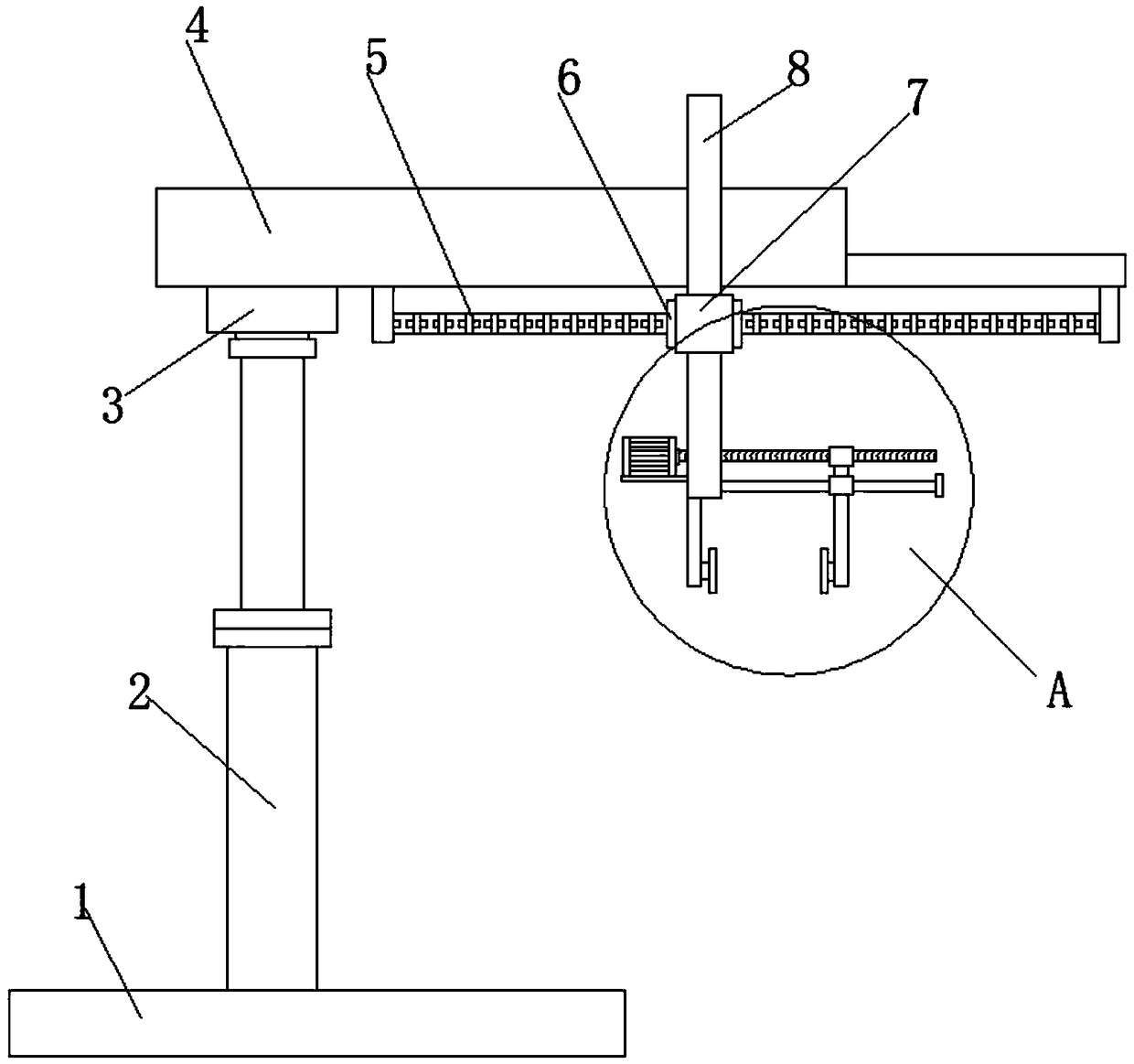
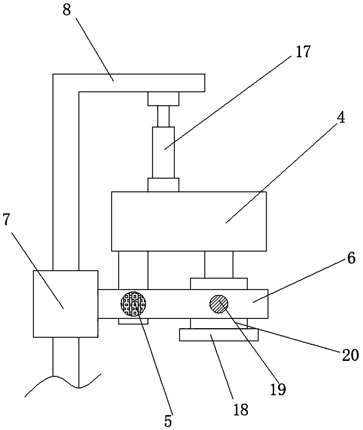
[0021] Reference Figure 1-3 , A discharging mechanical arm of an injection molding machine, comprising a fixed base 1, a telescopic column 2 is vertically arranged above the fixed base 1, a rotating plate 3 is provided on the top of the telescopic column 2, and the top of the telescopic column 2 is fixed by screws There is a rotating motor, and the output shaft of the rotating motor is connected with a rotating plate 3 through a coupling. A top plate 4 is horizontally connected above the rotating plate 3, and a first guide rod 5 is horizontally arranged below the top plate 4 along the length direction. A moving block 6 is provided on a gui...


PUM


Abstract

The invention discloses a discharging mechanical arm of an injection moulding machine. The discharging mechanical arm comprises a fixing pedestal, wherein a telescopic vertical column is vertically arranged above the fixing pedestal; a rotating plate is arranged on the top of the telescopic vertical column; a top plate is horizontally connected to the upper side of the rotating plate; a first guide rod is vertically arranged below the top plate and in the length direction; a moving block is arranged on the first guide rod; a mounting plate is connected to one end of the bottom of the top platethrough a connecting rod; a second motor is fixed to the mounting plate through screws; a second screw rod is connected to an output shaft of the second motor through a shaft coupler; the second screw rod and the first guide rod are parallel to each other; a moving guide ring is welded to one side of the moving block. The discharging mechanical arm rapidly clamps a workpiece through a movable plate and a fixed plate and clamps the workpiece in an adsorbing manner through sucking discs, so that the workpiece is firmly fixed, removal of the workpiece is facilitated and damage of the workpiece is effectively avoided; in addition, the workpiece removing operation is simple, convenient and fast, the workpiece removing time is short, and thus the production efficiency is effectively improved.

Description

technical field [0001] The invention relates to the technical field of injection molding machine unloading, in particular to an unloading mechanical arm of an injection molding machine. Background technique [0002] Injection molding machine is also known as injection molding machine or injection machine. It is the main molding equipment for making thermoplastics or thermosetting plastics into various shapes of plastic products using plastic molding molds. Divided into vertical, horizontal, all-electric. The injection molding machine heats the plastic, applies high pressure to the molten plastic, and makes it shoot out to fill the mold cavity. When the existing injection molding machine processes the workpiece thermoplastically, it is usually inconvenient to operate when taking out and unloading the processed workpiece, it takes a long time to take out, and the temperature of the injection molding machine is relatively high during the taking out process, usually There is ...

Claims


Application Information

Patent Timeline
IPC IPC(8): B29C45/42
Inventor 段玉珍
Owner JINGDE COUNTY HANHAI NEBULA INTELLIGENTIZE TECH RES & DEV CO LTD
Learn More