A kind of safe venous indwelling needle
A kind of venous indwelling needle, safe technology, applied in the field of medical devices, can solve the problems of lower puncture success rate, difficult to see blood return, poor stability, etc.
- Summary
- Abstract
- Description
- Claims
- Application Information
AI Technical Summary
Problems solved by technology
Method used
Image
Examples
Embodiment 1
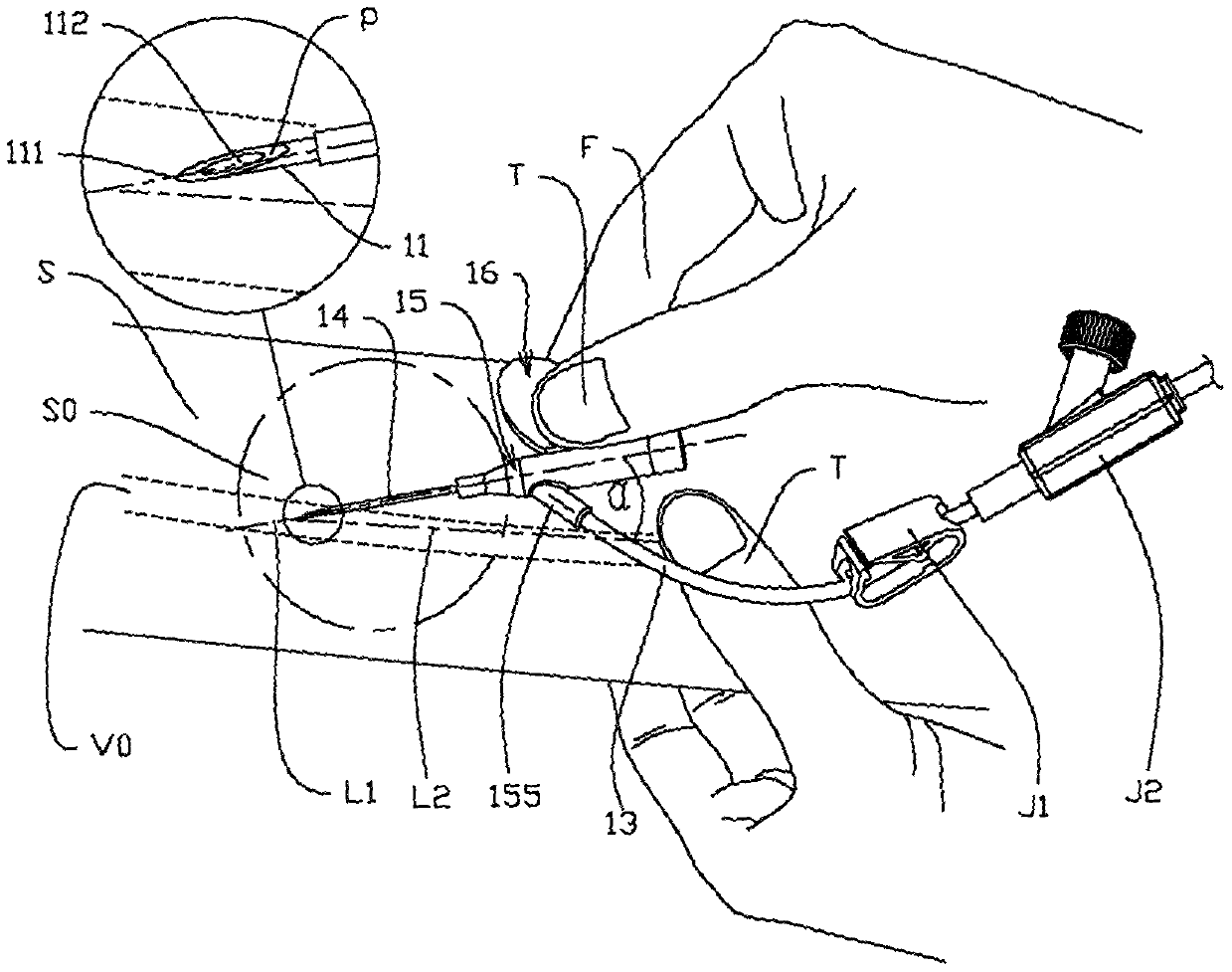
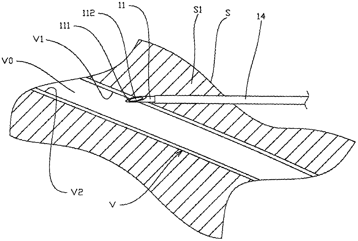
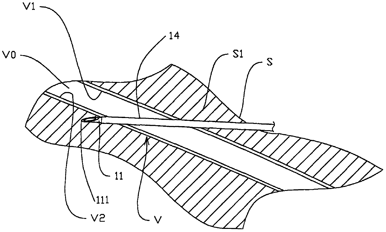
[0095] Such as Figure 3A , 3B As shown in the accompanying drawings at the beginning of the 3 characters, Embodiment 1 of the present invention includes: a rigid needle tube 11 for puncturing skin and vein walls, a needle tube base 12 that fixes the needle tube bottom part 114 therein; a flexible Sleeve 14, a casing seat 15 sealingly connected with casing bottom 142, casing seat 15 has a main body 151, casing seat upper end 153, casing seat side 154, casing seat top 152 and casing The bottom end 142 is airtightly connected, and there is a hollow side branch 155 on the left side of the sleeve seat main body 151 connected with the infusion hose 13. After the side branch 155 on the sleeve seat main body 151 is a cylindrical extension 156, such as Figure 3C , 3D As shown; the top part 121 of the needle tube base 12 is located behind the side branch 155 on the sleeve base body 151, and the needle tube base 12 also has an upper end surface 122, a lower end portion 123, a side su...
Embodiment 2
[0106] Such as Figure 4A , 4B As shown, the difference from the solution of Embodiment 2 is that it also includes a blade-shaped lateral extension 166 connected to the front end 161 of the vertical portion 165 of the vertical needle tube holder handle 16a; the lateral extension 166 can make the finger contact with the finger It can prevent the needle tube base 12 from moving backward due to the elastic restoring force generated by the release of the elastic potential energy of the elastic member 18. The "rear" also refers to the direction opposite to the movement of the sleeve base 15; specifically, two perpendicular The handles 16a1 and 16a2 of the needle tube base are connected with lateral extensions 166, and the thumb T and index finger F are against the inner surface of the lateral extensions 166, and the lateral extensions 166 can effectively prevent the movement of the needle base 12 to the rear; The function of finger rest 1252 can be replaced.
Embodiment 3
[0108] Such as Figure 5A , 5B As shown, the difference from the solution of Embodiment 2 is that it also includes a blade-shaped lateral extension 166 connected to the front end 161 of the vertical portion 165 of the vertical needle tube holder handle 16a and a backward curved portion connected to the lateral extension 166. Fold 1661. The setting of the backward bending part 1661 makes the ends of the two fingers of the operator sandwiched between the vertical part 165 and the backward bending part 1661 of the corresponding needle tube holder handle. This finger-clip handle structure not only makes the manipulation stable The flexibility is further improved and the fingers can actively release the binding force of the contact part 17 of the needle tube seat handle 16 on the sleeve seat extension 156 by pushing the backward bending part 1661, thereby releasing the elastic potential energy of the elastic part 18 faster.
[0109] Figure 5BThe partially cut perspective explod...
PUM
 Abstract
Description
Claims
Application Information
 - R&D
- Intellectual Property
- Life Sciences
- Materials
- Tech Scout
- Unparalleled Data Quality
- Higher Quality Content
- 60% Fewer Hallucinations
Browse by: Latest US Patents, China's latest patents, Technical Efficacy Thesaurus, Application Domain, Technology Topic, Popular Technical Reports.
© 2025 PatSnap. All rights reserved.Legal|Privacy policy|Modern Slavery Act Transparency Statement|Sitemap|About US| Contact US: help@patsnap.com


