
Multi-truss wood truss assembling equipment

A technology for assembling equipment and wooden trusses, which is applied to wood processing equipment, fixed drilling machines, manufacturing tools, etc., can solve the problems of high labor intensity, low production efficiency, and low efficiency, so as to reduce labor intensity, improve assembly quality, The effect of improving assembly efficiency

Active Publication Date: 2018-08-21
烟台博海木工机械有限公司
View PDF7 Cites 0 Cited by
  • Summary
  • Abstract
  • Description
  • Claims
  • Application Information

AI Technical Summary

Problems solved by technology

There are two fatal shortcomings in this production method: positioning, drilling, and pinning are carried out through manual assembly. Affected by the proficiency of workers and the quality of assembly, the strength of the multi-truss designed by calculation is often compared with the strength of the actual produced wood truss. The error is very large, which greatly reduces the strength of the multi-wood truss; because it is a purely manual operation, it needs to be positioned first, then drilled, and finally installed with pins. If the entire process is completed manually, it is obviously extremely inefficient and the assembly quality is not high. , so the existing assembly process generally cooperates with positioning tooling, punching tooling and pinning tooling to ensure the quality of assembly. Even so, the production efficiency is not high, and the labor intensity is also large, resulting in a large error between design and actual production. , so that the strength of multi-wood trusses is greatly reduced

Method used


Image

  • Multi-truss wood truss assembling equipment
  • Multi-truss wood truss assembling equipment
  • Multi-truss wood truss assembling equipment

Examples


Embodiment Construction

[0061] The principles and features of the present invention are described below in conjunction with examples, which are only used to explain the present invention and are not intended to limit the scope of the present invention.

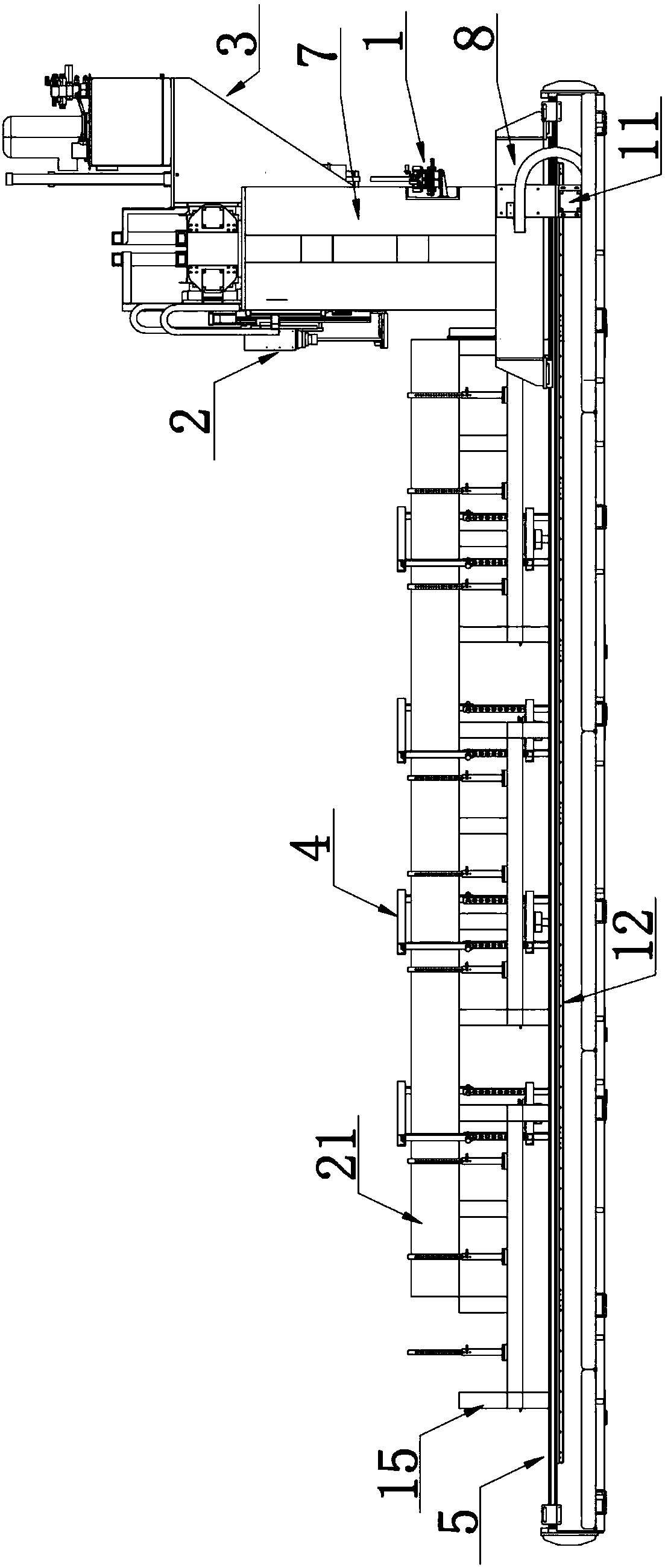
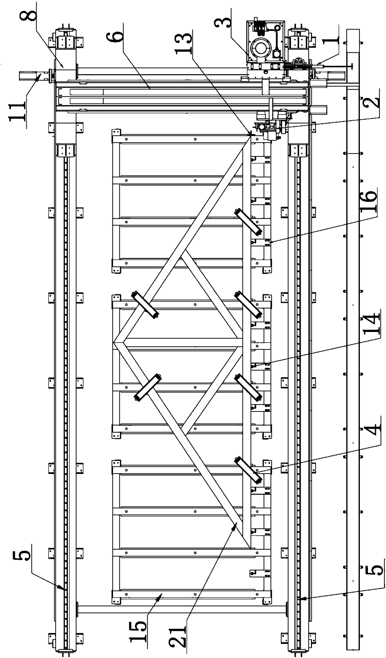
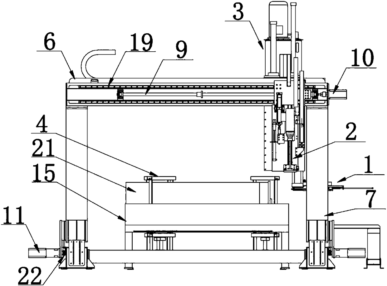
[0062] Such as Figure 1-Figure 11 As shown, a multi-truss assembling equipment includes a frame, a drilling mechanism arranged on the frame, a feeding mechanism and a grasping and pressing mechanism;

[0063] The frame includes a gantry longitudinal movement mechanism, and the gantry longitudinal movement mechanism includes a pair of longitudinal guide rails 5 arranged in parallel, a gantry frame arranged on the longitudinal guide rails, and a longitudinal power mechanism for driving the gantry frame to slide along the longitudinal guide rails. The gantry includes a beam 6 and a column 7 for supporting the beam, and the bottom of the column is provided with a sliding seat 8 matched with the longitudinal guide rail;

[0064] The feeding mechanism 1 ...


PUM


Abstract

The invention discloses multi-truss wood truss assembling equipment. The multi-truss wood truss assembling equipment comprises a rack, a drilling mechanism, a feeding mechanism and a pressing pin grabbing mechanism, and the drilling mechanism, the feeding mechanism and the pressing pin grabbing mechanism are arranged on the rack; the rack comprises a longitudinal gantry moving mechanism, the longitudinal gantry moving mechanism comprises a pair of longitudinal guide rails, a portal frame and a longitudinal power mechanism, the portal frame comprises a cross beam and stand columns used for supporting the cross beam, and sliding bases matched with the longitudinal guide rails are arranged at the bottoms of the stand columns; and the feeding mechanism is arranged on the stand columns, and thedrilling mechanism and the pressing pin grabbing mechanism are connected with the cross beam through a transverse moving mechanism. The multi-truss wood truss assembling equipment can automatically move to corresponding machining positions according to the assembling requirements to achieve automatic drilling and pin assembling integration operation of a multi-truss wood truss, the error requirements in design and practical production are met, therefore, the assembling efficiency of the multi-truss wood truss is improved, the labor intensity is reduced, and the assembling quality of the multi-truss wood truss is improved.

Description

technical field [0001] The invention relates to multi-truss assembling equipment, which belongs to the technical field of wood truss processing. Background technique [0002] Due to its excellent performance, light wood trusses are widely used in the roof and floor systems of modern wooden structures and urban "slope conversion" projects; in light wood structures, in some heavy-duty structures, single wood trusses It can no longer meet the design needs, and needs to be solved with multi-truss wood trusses. Multi-truss trusses are composed of multiple pieces of single-truss through connectors. Multi-timber trusses are generally used in key parts of roof or floor systems. The stress environment of the concentrated load transmitted by the lapped common single-truss is more complex than that of the common single-truss. This kind of multi-truss, which is composed of multiple single-trusses, has also become the most commonly used structural form at the key load-bearing nodes of ...

Claims


Application Information

Patent Timeline
Patent Type & Authority Applications(China)
IPC IPC(8): B27M3/00B27C3/02
CPCB27C3/02B27M3/0073
Inventor 黄涛
Owner 烟台博海木工机械有限公司
Learn More