
Pressure sensor patch pressurization device

A pressure sensor and pressurizing equipment technology, applied in mechanical equipment, measuring fluid pressure, instruments, etc., can solve the problems of inconsistent zero position output and different strength of sensors, and achieve the effect of simple structure, convenient operation, and cost-saving output.

Inactive Publication Date: 2018-08-17
江琴兰
View PDF0 Cites 3 Cited by
  • Summary
  • Abstract
  • Description
  • Claims
  • Application Information

AI Technical Summary

Problems solved by technology

[0004] The purpose of the present invention is to solve the shortcomings of inconsistent zero output of the sensor caused by the inconsistent strength of the manual patch installation in the prior art, and propose a pressure sensor patch pressurization device

Method used


Image

  • Pressure sensor patch pressurization device
  • Pressure sensor patch pressurization device
  • Pressure sensor patch pressurization device

Examples


Embodiment Construction

[0018] The following will clearly and completely describe the technical solutions in the embodiments of the present invention with reference to the accompanying drawings in the embodiments of the present invention. Obviously, the described embodiments are only some, not all, embodiments of the present invention.

[0019] In describing the present invention, it should be understood that the terms "upper", "lower", "front", "rear", "left", "right", "top", "bottom", "inner", " The orientation or positional relationship indicated by "outside", etc. is based on the orientation or positional relationship shown in the drawings, and is only for the convenience of describing the present invention and simplifying the description, rather than indicating or implying that the referred device or element must have a specific orientation, so as to Specific orientation configurations and operations, therefore, are not to be construed as limitations on the invention.

[0020] refer to Figure ...


PUM


Abstract

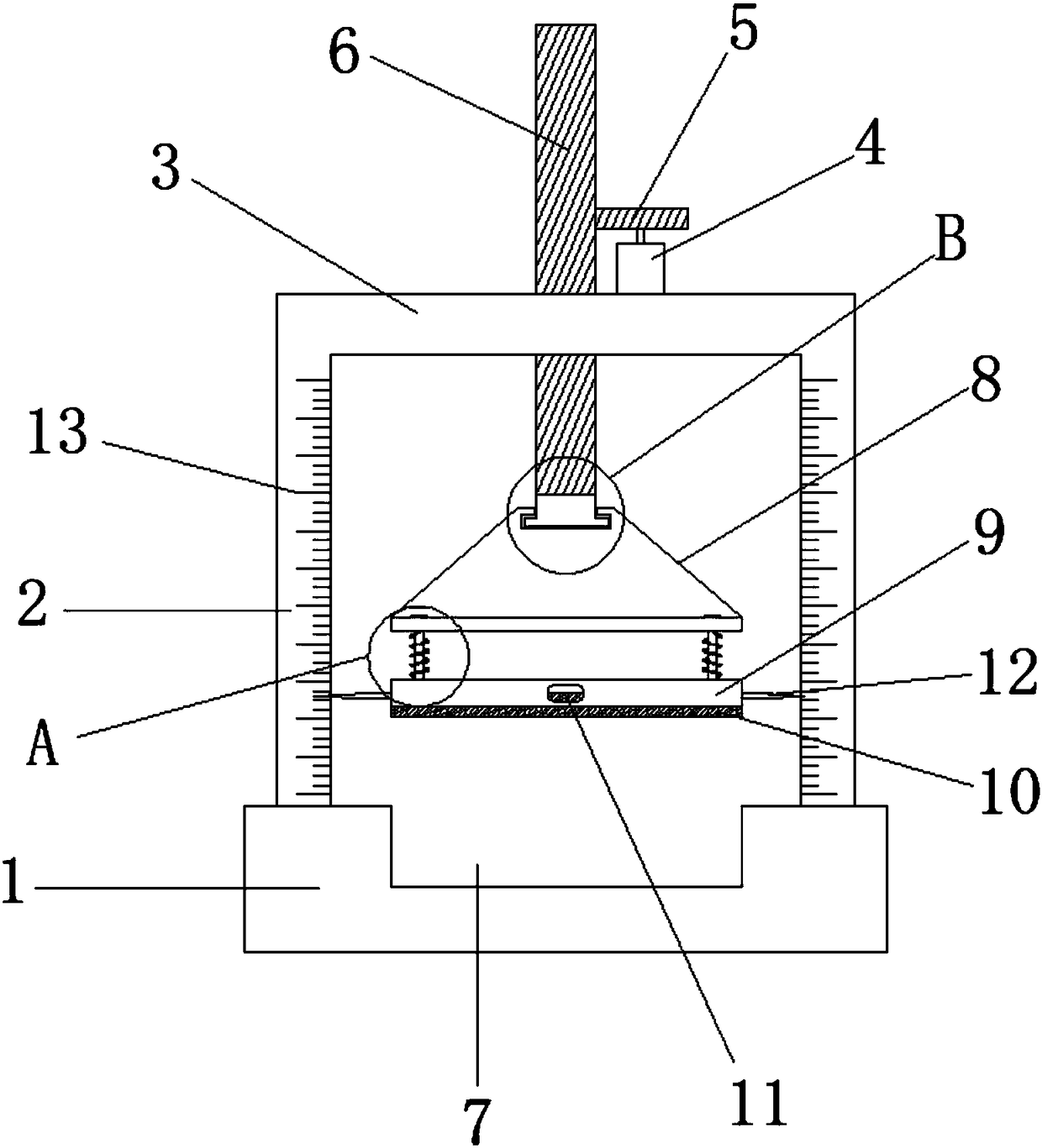
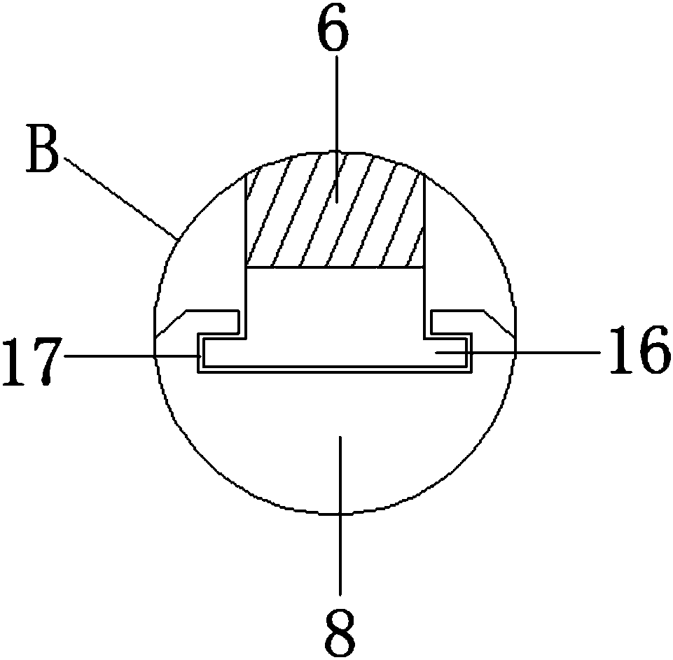
The invention discloses a pressure sensor patch pressurization device. The device comprises a base, two vertical plates are symmetrically arranged on the top wall of the base, the top ends of the twovertical plates are jointly provided with a transverse plate, a motor is arranged on the top wall of the transverse plate, a bevel gear is arranged at the driving end of the motor, the side wall of the bevel gear is meshed with a bevel gear rod, the bevel gear rod penetrates through the top wall of the transverse plate and extends to the lower side of the transverse plate, a trapezoid block is arranged at the bottom end of the bevel gear rod, a rotary groove is formed in the top of the trapezoid block, the bottom end of the bevel gear rod penetrates through the top wall of the trapezoid blockand extends into the interior of the rotary groove. According to the device, the structure is simple, the operation is convenient, by accurately controlling the pressure applied to a sensor patch, thesituation that zero-position output is inconsistent after the sensor patch is installed can be avoided, so that the sensor does not need to be corrected, and the cost output is saved.

Description

technical field [0001] The invention relates to the technical field of pressure sensors, in particular to pressure sensor patch pressurization equipment. Background technique [0002] A pressure sensor is a device or device that can sense pressure signals and convert the pressure signals into usable output electrical signals according to certain rules. A pressure sensor usually consists of a pressure sensitive element and a signal processing unit. According to different test pressure types, pressure sensors can be divided into gauge pressure sensors, differential pressure sensors and absolute pressure sensors. Pressure sensor is the most commonly used sensor in industrial practice. It is widely used in various industrial automatic control environments, involving water conservancy and hydropower, railway transportation, intelligent buildings, production automatic control, aerospace, military industry, petrochemical, oil wells, electric power, ships, machine tools , pipeline...

Claims


Application Information

Patent Timeline
Patent Type & Authority Applications(China)
IPC IPC(8): F16B11/00G01L1/00G01L19/00
CPCF16B11/00F16B11/004G01L1/00G01L19/00
Inventor 江琴兰
Owner 江琴兰
Learn More