Eureka AIR delivers breakthrough ideas for toughest innovation challenges, trusted by R&D personnel around the world.

Pasty material conveying device and pasty material conveying system

A technology for conveying devices and materials, which is applied to conveyor control devices, conveyor objects, transportation and packaging, etc., can solve problems such as high cost and complex structure, and achieve the effect of semi-automatic quantitative transportation.

Pending Publication Date: 2018-08-17
翁源惜福环保科技有限公司
View PDF0 Cites 1 Cited by
  • Summary
  • Abstract
  • Description
  • Claims
  • Application Information

AI Technical Summary

Problems solved by technology

[0005] One of the objectives of the present invention is to provide a slurry material conveying device, which solves the problem that the quantitative detection device for slurry conveying in the related art needs sensors to monitor the amount of slurry, and also cooperates with a power device for control, which has a complex structure and high cost. technical problem
[0006] The second object of the present invention is to provide a slurry material conveying system, which solves the problem that the quantitative detection device for slurry conveying in the related art needs sensors to monitor the amount of slurry, and it also needs to be controlled with a power device, which has a complicated structure and high cost. technical problem

Method used


Image

  • Pasty material conveying device and pasty material conveying system
  • Pasty material conveying device and pasty material conveying system
  • Pasty material conveying device and pasty material conveying system

Examples


Embodiment 1

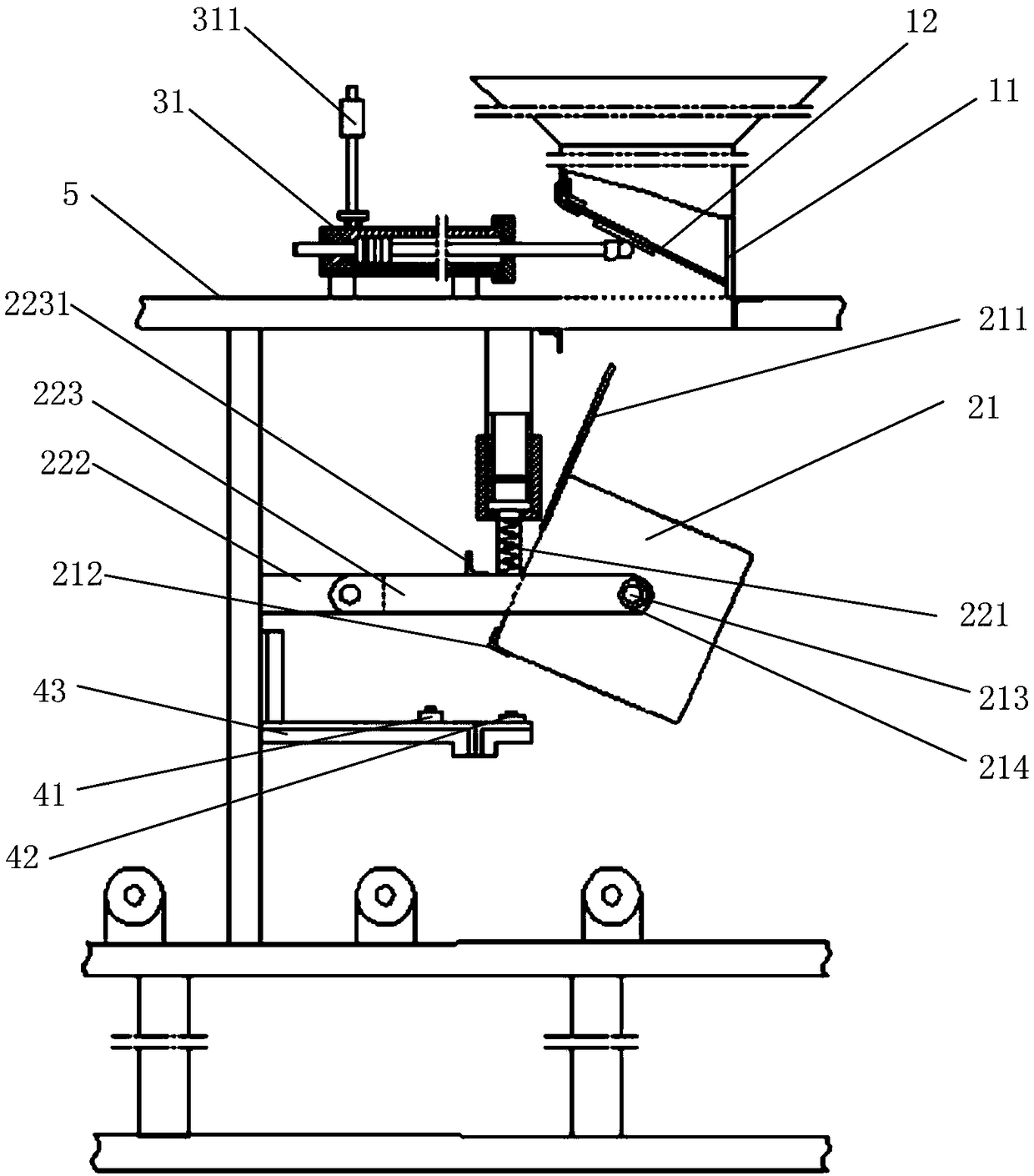
[0048] refer to figure 1 -3. The embodiment of the present invention provides a slurry material conveying device, including: a frame 5, a feeding unit, a transfer unit, and a control unit;

[0049] The feeding unit is arranged above the transfer unit, and is used to introduce upstream materials into the transfer barrel 21;

[0050] Wherein, the transfer unit includes an elastic mechanism and a transfer barrel 21, the elastic mechanism is arranged on the frame 5, and the transfer barrel 21 is eccentrically hinged on the elastic mechanism;

[0051] The transfer barrel 21 can rotate around the hinge point to switch between the receiving state and the dumping state;

[0052] The control unit is arranged opposite to the transfer barrel 21, and is used to control the feeding or cutting of the feeding unit according to the action of the transfer barrel 21.

[0053] The transfer unit is used to temporarily accept the materials conveyed by the feeding unit, and at the same time trigg...

Embodiment 2

[0093] An embodiment of the present invention provides a slurry material conveying system, including the above slurry material conveying device.

[0094] Wherein, the specific structure of the slurry material conveying device has been introduced in detail above, and will not be repeated here.

[0095] The system may also include a feeding device and a feeding device, wherein the feeding device is used to deliver materials to the feeding unit, and the feeding device is used to transfer the materials in the tray.

[0096] It can be seen that all the beneficial effects of the above-mentioned slurry material conveying device can be obtained, semi-automatic quantitative delivery of slurry materials can be realized, production costs can be reduced, and production efficiency can be improved.


PUM


Abstract

The invention relates to the technical field of pasty material production, in particular to a pasty material conveying device and a pasty material conveying system. The pasty material conveying devicecomprises a rack, a feeding unit, a transferring unit and a control unit, wherein the transferring unit comprises an elastic mechanism and a transferring feed cylinder; the elastic mechanism is arranged on the rack; the transferring feed cylinder is eccentrically hinged onto the elastic mechanism, and can rotate around a hinged point so as to switch between a holding state and an inclining state;the feeding unit is arranged above the transferring unit and is used for guiding an upstream material into the transferring feed cylinder; and the control unit is arranged opposite to the transferring feed cylinder, and is used for controlling the feeding unit to feed or cut materials according to the action of the transferring feed cylinder. The whole pasty material conveying device is simple instructure, low in cost, reliable in mechanical structure action, and capable of semi-automatically and quantitatively conveying the pasty materials.

Description

technical field [0001] The invention relates to the technical field of slurry material production, in particular to a slurry material conveying device and a slurry material conveying system. Background technique [0002] The existing slurry conveying adopts a straight up and down structure, quantitatively pours into the slurry pan through a quantitative detection device, and then pours out the slurry in the slurry pan. [0003] The quantitative detection device needs sensors to monitor the amount of slurry, and also cooperates with the power device for control, which has a complex structure and high cost. [0004] The information disclosed in this Background section is only intended to enhance the understanding of the general background of the present invention, and should not be considered as an acknowledgment or any form of suggestion that the information constitutes the prior art that is already known to those skilled in the art. Contents of the invention [0005] One ...

Claims


Application Information

Patent Timeline
IPC IPC(8): B65G65/32B65G65/23B65G43/00
CPCB65G43/00B65G65/23B65G65/32
Inventor 扈华庚黄宗彩沈伟航
Owner 翁源惜福环保科技有限公司
Why Eureka
Eureka Blog
Learn More