A special punching mechanism for office supplies
A technology for office supplies and countersinking, applied in the field of punching, can solve the problems of insufficient paper adaptability, dangerous punching, affecting work efficiency, etc., to achieve high practicability and versatility, reduce operating costs, and simple components.
- Summary
- Abstract
- Description
- Claims
- Application Information
AI Technical Summary
Problems solved by technology
Method used
Image
Examples
Embodiment 1
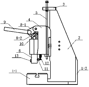
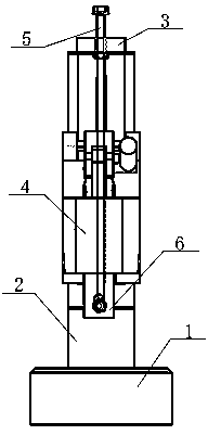
[0025] as attached Figure 1-6 As shown, the punching mechanism includes a punching base 1, a punching pillar 2, a positioning plate 3, a positioning block 4, a screw 5, a punching driving body 6, a punching punch 7, a connecting rod group 8, a handle 9, The first pin 10 , the second pin 11 , and the extension spring 12 .
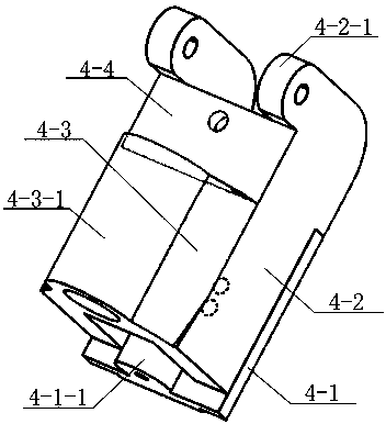
[0026] The perforated base 1 includes a front seat 1-1 and a rear seat 1-2, and a placement space is formed between the front seat 1-1 and the rear seat 1-2. The perforated pillar 2 is arranged in the placement space, and the top of the perforated pillar 2 A positioning plate 3 is provided, and the positioning plate 3 is provided with through screw holes, and the middle part of the perforated pillar 2 is fixedly provided with a positioning block 4 .
[0027] The front part of the front seat 1-1 of the punching base 1 is a placement boss, and the placement boss is provided with a "T" type chip discharge port. The front portion of the rear seat 1-1 is splic...
Embodiment 2
[0036] In this embodiment, as a further embodiment of Example 1, the special punching mechanism for office supplies is detachable, and the steps for using the special punching mechanism for office supplies are as follows:
[0037] A. The front seat and the rear seat of the perforated base are spliced into a whole through the connecting piece, and then the perforated pillar is fixedly connected between the front seat and the back seat through the connecting piece to form a storage space, and then the positioning plate is connected to the punched through the connecting piece. hole the top of the strut,
[0038] B. Pass the lead screw through the screw hole of the positioning plate from top to bottom, and connect the fixing nut to the lead screw close to the lower end surface of the positioning plate,
[0039] C. Align the threaded through hole of the semicircular convex seat of the positioning block with the bottom of the lead screw, and pass upwards. When the scale on the ...
PUM
 Abstract
Description
Claims
Application Information
 - R&D Engineer
- R&D Manager
- IP Professional
- Industry Leading Data Capabilities
- Powerful AI technology
- Patent DNA Extraction
Browse by: Latest US Patents, China's latest patents, Technical Efficacy Thesaurus, Application Domain, Technology Topic, Popular Technical Reports.
© 2024 PatSnap. All rights reserved.Legal|Privacy policy|Modern Slavery Act Transparency Statement|Sitemap|About US| Contact US: help@patsnap.com


