
Testing device and method for simulating movement of density current in canyon

A test device and the technology of the differential density flow, which is applied in the field of the test device for simulating the movement of the differential density flow in the canyon, can solve the problems of numerous device model components, high test cost, complex structure, etc., and achieve flexible component combination design and experimental operation Simple and stable structure

Pending Publication Date: 2018-08-14
ZHEJIANG UNIV
View PDF5 Cites 9 Cited by
  • Summary
  • Abstract
  • Description
  • Claims
  • Application Information

AI Technical Summary

Problems solved by technology

[0004] Among the published patent schemes, various flume systems for hyperpycnal flow research have been given at home and abroad, but the flume systems are all rectangular cross-sections, which have limitations for simulating hyperpycnal flow in canyons, while this experimental device adopts polygonal cross-sections. It is rectangular, and the lower part is an isosceles trapezoid, which is highly comparable to the canyon shape; most of the hyperpycnal flow tests that have been carried out have many components and complex structures in the device model, and the model needs to be remade in each test process. Excessive test costs and other issues; at the same time, in the existing model test design, there are few technical solutions for the flow process device that considers the flow process device when the hyperpycnal flow encounters vegetation and sudden changes in terrain

Method used


Image

  • Testing device and method for simulating movement of density current in canyon
  • Testing device and method for simulating movement of density current in canyon
  • Testing device and method for simulating movement of density current in canyon

Examples


Embodiment Construction

[0049] In order to make the object, technical solution and advantages of the present invention clearer, the present invention will be further described in detail below in conjunction with the accompanying drawings and embodiments. It should be understood that the specific embodiments described here are only used to explain the present invention, not to limit the present invention. In addition, the technical features involved in the various embodiments of the present invention described below can be combined with each other as long as they do not constitute a conflict with each other.

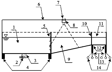
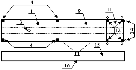
[0050]As shown in the figure, a test device for simulating the movement of a hyperpycnal flow in a canyon includes a flat slope tank 1, a slope tank 9, a water storage tank 11, a laser instrument 8, a CCD camera 16, a gate 10 and a hydraulic jack 12; The water tank 1 and the slope water tank 9 are directly connected in a hinged manner, and the slope water tank 9 and the water storage tank 11 are...


PUM


Abstract

The invention discloses a testing device and method for simulating movement of a density current in a canyon. The device comprises a flat water tank, an oblique water tank, a laser instrument, a CCD camera, a hydraulic jack, a bearing platform, a water discharge guide pipe, a valve switch, a pulley, a guide rod, a guide rail and a calibrated scale. The testing method for simulating the movement ofthe density current in the canyon comprises the following steps of test building, testing, test device arrangement and data analysis. The device has the advantages that the structure is simple, the cost is low, the functions are diversified, the device can be suitable for various working conditions, and the testing precision is high; the flowing process of the density current in the canyon underthe abrupt change conditions of vegetation and terrain can be simulated, the testing process is convenient to operate, the testing efficiency is high, and the testing design is flexible. The testing result can provide data for research on the hydrodynamic characteristic of the density current and has a high reference value.

Description

technical field [0001] The invention relates to a water conservancy test tank system, in particular to a test device and method for simulating the movement of a hyperpycnal flow in a canyon. Background technique [0002] Density flow, also known as density flow, is a phenomenon in which one of the fluids flows along the interface due to the difference in density, and does not globally mix with other fluids during the flow process. Phenomena of hyperpycnal flow are very common in nature and engineering, such as temperature drainage of power plants, salt water wedges in estuary areas, sand discharge from reservoirs, sandstorms, and avalanches. Density flow can be divided into three types according to the formation reasons: temperature difference density flow, salinity difference density flow, particle density flow. [0003] Hyperpycnal flow is universal and important in nature and engineering, and plays a very important role in national economic construction and environmental...

Claims


Application Information

Patent Timeline
IPC IPC(8): G01M10/00
CPCG01M10/00
Inventor 林颖典熊杰刘雅钰韩东睿钱煜鹏袁野平
Owner ZHEJIANG UNIV
Learn More