
Oil-water separating equipment for recycling treatment of organic wastes

A technology for oil-water separation and organic waste, applied in liquid separation, separation methods, flotation water/sewage treatment, etc., can solve the problems of limited aeration range, key failure, leakage, etc., to improve practicability and reliability, prolong The effect of service life and power cost saving

Inactive Publication Date: 2018-08-14
夏士桀
View PDF0 Cites 7 Cited by
  • Summary
  • Abstract
  • Description
  • Claims
  • Application Information

AI Technical Summary

Problems solved by technology

[0003] In the process of resourceful treatment of organic waste, oil-water separation of organic waste is required. Air flotation machine is a common oil-water separation equipment used for resourceful treatment of organic waste. However, the existing air flotation machine is in the process of actual use There are still some deficiencies in it. For example, the aeration devices of the existing air flotation machines are almost all fixedly installed at the water inlet pipe, the aeration range is limited, and the air bubbles cannot fully contact with the oil in the waste water. In addition, the air flotation machines When the scraper scrapes off oil residue, some oil residue will flow out from both ends of the scraper plate, resulting in incomplete removal of oil residue, requiring multiple scraping treatments, which greatly reduces the effect of oil residue removal. In addition, the current The control panels of some air flotation machines are installed on one side of the air flotation machine. When the air flotation machine is installed outdoors in rainy days, the control panel is easy to be wet by rain, which will cause the keys to fail, and even leakage, etc., causing The damage of the equipment affects the service life of the equipment, and these problems greatly reduce the practicability and reliability of the oil-water separation equipment

Method used


Image

  • Oil-water separating equipment for recycling treatment of organic wastes
  • Oil-water separating equipment for recycling treatment of organic wastes
  • Oil-water separating equipment for recycling treatment of organic wastes

Examples


Embodiment Construction

[0029] The present invention is described in further detail now in conjunction with accompanying drawing. These drawings are all simplified schematic diagrams, which only illustrate the basic structure of the present invention in a schematic manner, so they only show the configurations related to the present invention.

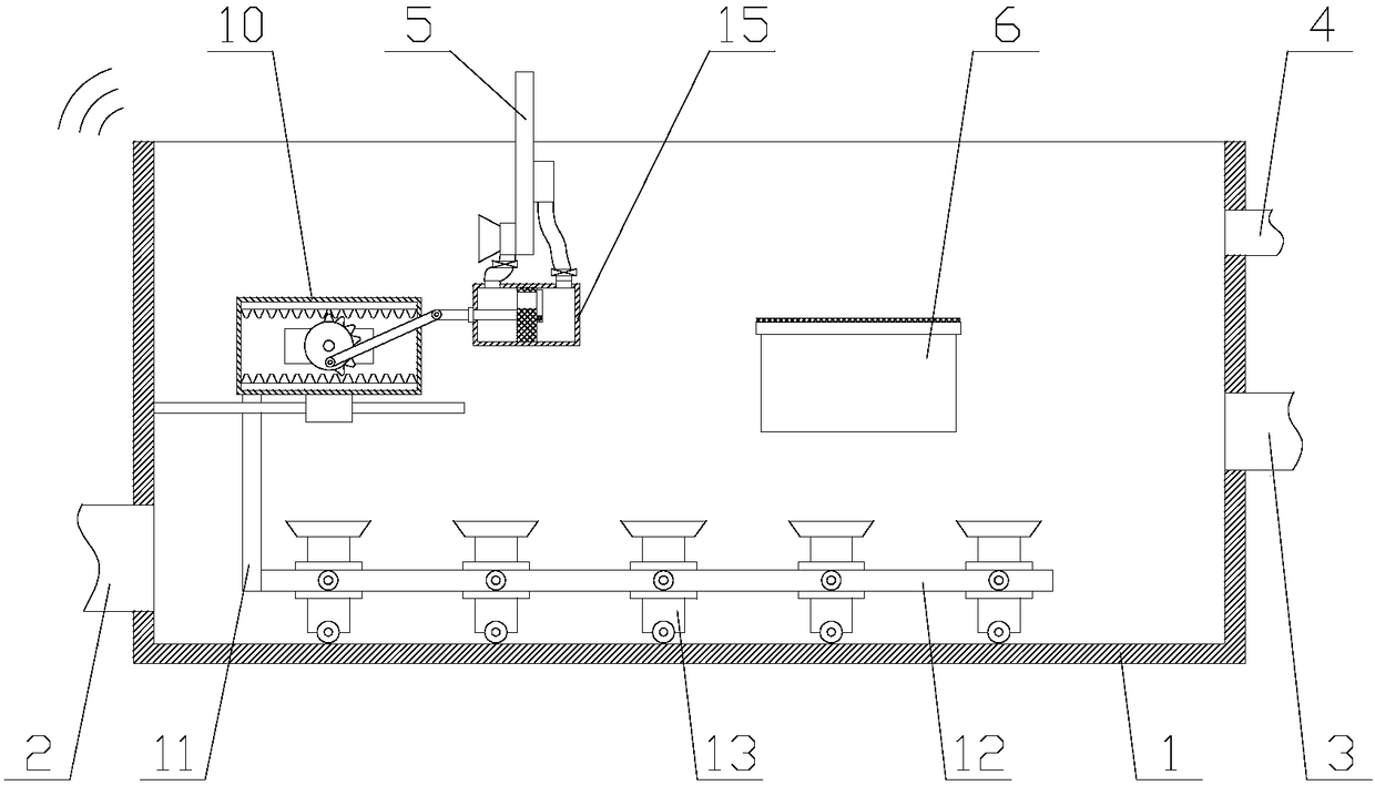
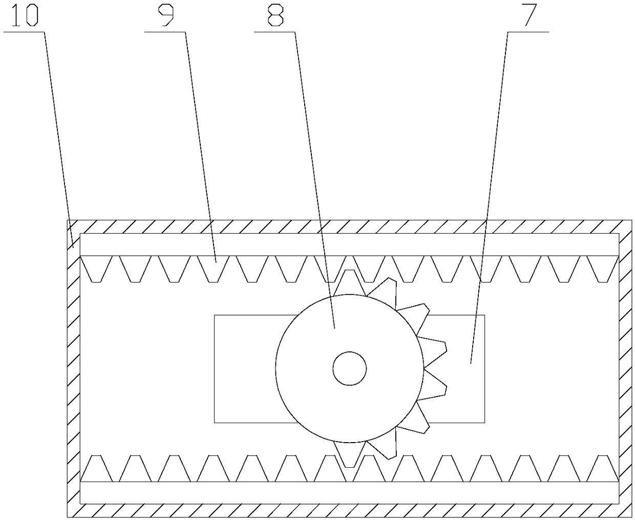
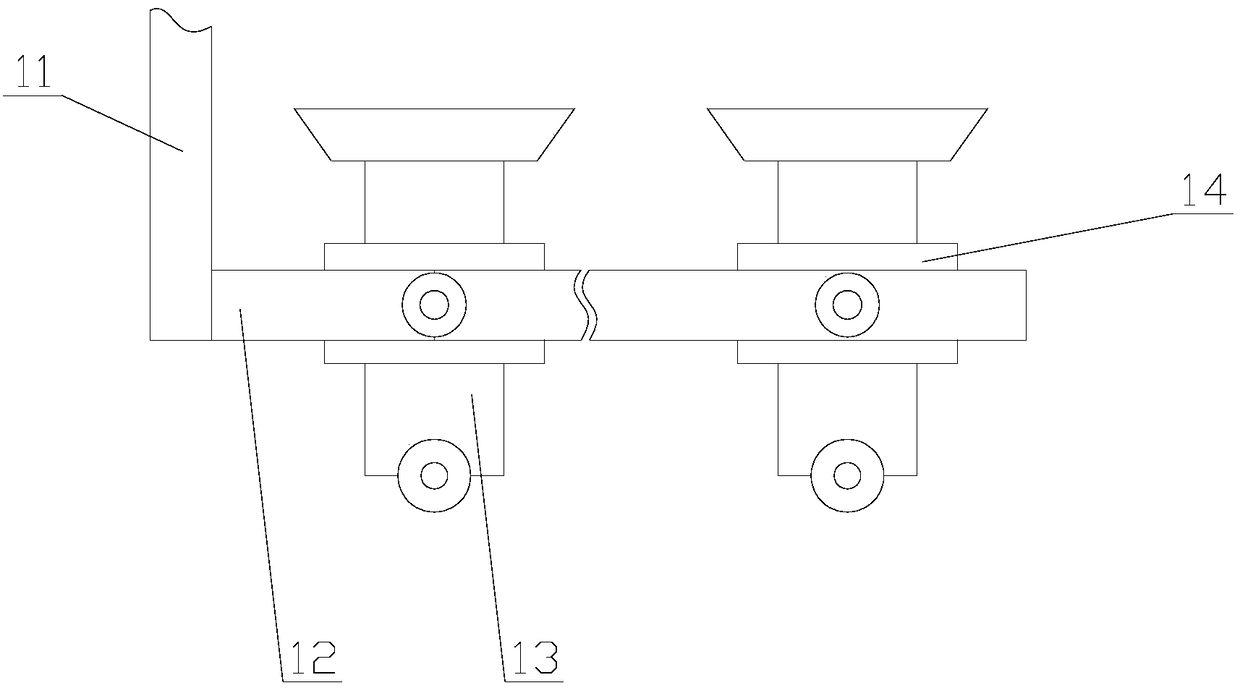
[0030] Such as figure 1 As shown in the figure, an oil-water separation device for recycling organic waste, including a main body 1, a water inlet pipe 2, a water outlet pipe 3, an oil discharge pipe 4, a slag scraper 5 and a control panel 6, and also includes a processing mechanism and a rain-shielding mechanism , the rain-shielding mechanism is arranged above the control panel 6;

[0031] Through the treatment mechanism, the aeration range is expanded, so that the oil in the sewage can fully contact with the air, and it can also prevent the oil residue from leaking during the scraping process. Compared with the existing air flotation machine, the effect of ...


PUM


Abstract

The invention relates to oil-water separating equipment for recycling treatment of organic wastes. The oil-water separating equipment comprises a main body, a water feeding pipe, a water discharging pipe, an oil discharging pipe, a slag scraping plate and a control panel and also comprises a treating mechanism and a rain shielding mechanism, wherein the treating mechanism comprises a driving component, a gas filling component and a slag absorbing component; the rain shielding mechanism comprises a cylinder, a moving block, a telescopic frame, a sliding block, a moving plate and rain shieldingcloth. The oil-water separating equipment for recycling treatment of the organic wastes has the beneficial effects that by the treating mechanism, not only is the aeration range expanded and oil stains in sewage can be fully contacted with air, but also leakage of oil slags in the slag scraping process can be prevented, the effect of oil-water separation is improved and the slag-removing working efficiency is improved; by the rain shielding mechanism, the control panel can be shielded, and a role in protecting the equipment can be played, so that the service life of the equipment is prolongedand the practicability and the reliability of the oil-water separating equipment are improved.

Description

technical field [0001] The invention relates to the field of resourceful treatment of organic waste, in particular to an oil-water separation device for resourceful treatment of organic waste. Background technique [0002] Organic waste, also known as wet waste, refers to waste containing organic components in domestic waste. Mainly paper, fiber, bamboo, wood, kitchen waste, etc. Waste recycling is to classify discarded waste and use it as recycled raw materials to make it a renewable resource. [0003] In the process of resourceful treatment of organic waste, oil-water separation of organic waste is required. Air flotation machine is a common oil-water separation equipment used for resourceful treatment of organic waste. However, the existing air flotation machine is in the process of actual use There are still some deficiencies in it. For example, the aeration devices of the existing air flotation machines are almost all fixedly installed at the water inlet pipe, the aera...

Claims


Application Information

Patent Timeline
Patent Type & Authority Applications(China)
IPC IPC(8): C02F1/40C02F1/24B01D17/035
CPCC02F1/40B01D17/0205C02F1/24
Inventor 夏士桀
Owner 夏士桀
Learn More