
Efficient tilting rotor-wing unmanned aerial vehicle

A technology for tilting rotors and unmanned aerial vehicles, which is applied in the field of aviation products, can solve the problems of low efficiency of vertical flight rotors, poor control performance of vertical flight headings, difficulty in vertical flight and flat flight status, etc., so as to improve control efficiency and improve endurance. effect of time

Inactive Publication Date: 2018-08-14
北京天宇新超航空科技有限公司
View PDF9 Cites 6 Cited by
  • Summary
  • Abstract
  • Description
  • Claims
  • Application Information

AI Technical Summary

Problems solved by technology

Although the tilt-rotor UAV can meet the application requirements of some special scenarios, there are still problems in practical applications such as low efficiency of the vertical flight rotor, slow level flight speed, and poor vertical flight heading control performance.
For example: 1. The vertical flight and level flight of existing tilt-rotor UAVs use the same set of power systems, and most of them are fixed-pitch propellers. There are significant differences in the mechanisms, which are determined by the different aerodynamic conditions of the propellers in different flight states. Therefore, it is difficult for the existing power system of the tilt-rotor UAV to be compatible with the vertical and horizontal flight states efficiently at the same time, and the speed of the horizontal flight is relatively low. Low; 2. Existing tilt-rotor UAV schemes mostly adopt multi-rotor vertical take-off and landing, and UAV heading control is realized through rotor speed or pitch control. However, in practical applications, the fuselage wing structure has a large windward area. The control force of the rotor anti-torque heading control is obviously insufficient, which leads to poor wind resistance of this type of UAV when flying vertically

Method used


Image

  • Efficient tilting rotor-wing unmanned aerial vehicle
  • Efficient tilting rotor-wing unmanned aerial vehicle
  • Efficient tilting rotor-wing unmanned aerial vehicle

Examples


Embodiment Construction

[0031] The technical solutions of the present invention will be described in further detail below in conjunction with specific embodiments. It should be understood that the specific embodiments described here are only used to explain the present invention, but not to limit the present invention.

[0032] In the description of the present invention, it should be understood that the terms "center", "longitudinal", "transverse", "upper", "lower", "front", "rear", "left", "right", " The orientation or positional relationship indicated by "vertical", "horizontal", "top", "bottom", "inner", "outer" etc. is based on the orientation or positional relationship shown in the drawings, and is only for the convenience of describing the present invention and The description is simplified, rather than indicating or implying that the pointed device or element must have a specific orientation, be constructed and operated in a specific orientation, and therefore cannot be understood as a limitatio...


PUM


Abstract

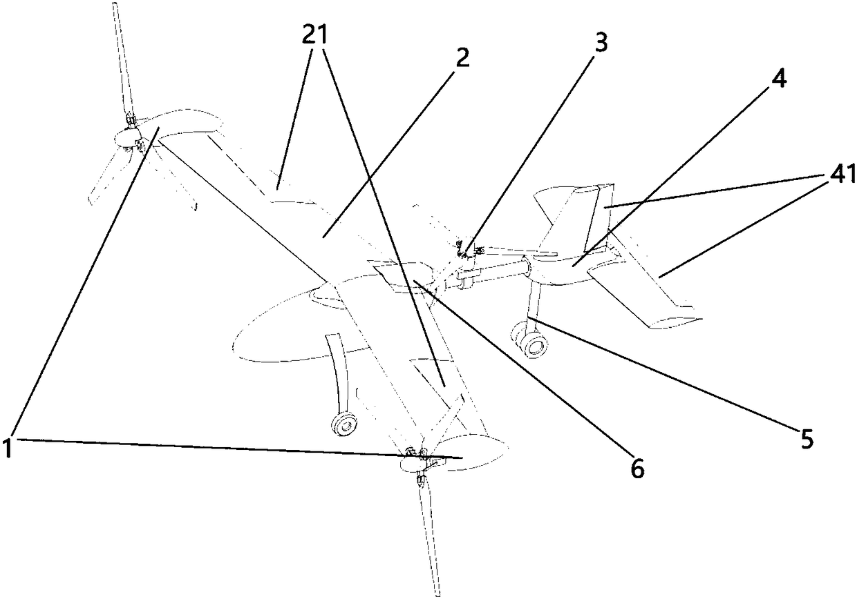
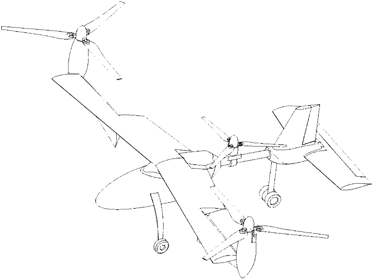
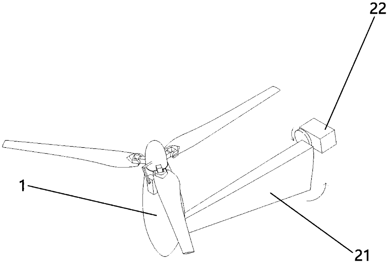
The invention discloses an efficient tilting rotor-wing unmanned aerial vehicle. The layout of the unmanned aerial vehicle has higher aerodynamic efficiency and control reliability; under the condition that vertical takeoff and landing are ensured, high-speed efficient level flight can be realized. The unmanned aerial vehicle comprises tilting rotor wings, a tail rotor wing, a wing, an empennage,a fuselage and an undercarriage. The unmanned aerial vehicle needs to go through a vertical flight state, a transition state and a level flight state from takeoff to level flight. The tilting rotor wings can tilt around a rotary shaft in a parallel wingspan direction; when the tilting rotor wings are at the vertical flight state, the tilting rotor wings and the tail rotor wing provide a lifting force and a posture control force to the unmanned aerial vehicle; in a level flight process, a forward pull force is provided; the tilting rotor wings have a variable distance and take account of rotorwing efficiency of the vertical flight state and the level flight state, and the unmanned aerial vehicle can be driven to fly at a high speed; the tilting rotor wings are mounted on left and right wingtips of the wing and shielding, caused by the wing, on downwash flow of the rotor wings at the vertical flight state can be effectively reduced and the flight efficiency is improved; the tilting rotor wings and ailerons at left and right sides are commonly deflected, so that the rolling operation efficiency of the level flight state is improved.

Description

Technical field [0001] The invention relates to a tilt-rotor drone, which belongs to the technical field of aviation products. Background technique [0002] Tilt-rotor unmanned aerial vehicles have both the multi-rotor vertical take-off and landing capability and the high-speed flight performance of a propeller fixed-wing aircraft, and belong to a vertical take-off and landing drone. Tilt-rotor UAVs can tilt the direction of dynamic force and have a wide range of application prospects. The main applications include logistics, line inspection, forest fire prevention, and environmental monitoring. Although the tilt-rotor UAV can meet the application requirements of some special scenarios, there are still problems in practical applications such as low vertical flying rotor efficiency, slow horizontal flight speed, and poor vertical flying heading control performance. For example: 1. Existing tilt-rotor UAVs use the same power system for vertical and horizontal flight, and most of t...

Claims


Application Information

Patent Timeline
Patent Type & Authority Applications(China)
IPC IPC(8): B64C27/22B64C27/32B64C27/52B64C11/30
CPCB64C11/30B64C27/22B64C27/32B64C27/52
Inventor 胡龙王一博
Owner 北京天宇新超航空科技有限公司
Learn More