Turnover type shot blasting machine for coil wire

A flip-type, shot blasting machine technology, which is applied in the direction of abrasive jetting machine tools, used abrasive processing devices, abrasives, etc., can solve the problems of good interlayer relationship damage, waste, and large wire rope spacing, etc., to achieve improved shot blasting efficiency effect

Pending Publication Date: 2018-08-14
UNIV OF JINAN
View PDF3 Cites 0 Cited by
  • Summary
  • Abstract
  • Description
  • Claims
  • Application Information

AI Technical Summary

Problems solved by technology

For the coiled wire, the two feeding methods have their own advantages and disadvantages. For the linear feeding after the coiled wire is unrolled, it needs to provide at least a supply end reel and a discharge end reel, and the wire needs to be tensioned. The machine takes up a lot of space
The key problem is that the diameter of the wire is relatively small, and the jet flow of the shot blaster is a conical jet flow from the exit of the shot blaster to the small end. On the contrary, most of the projectiles are air-launched, causing great waste
[0003] For the shot blasting of coiled wire rods, although the utilization rate of the projectile jet has been greatly improved, the wires in the inner layer of the wire will be blocked by the wires in the outer layer. cannot be blasted to
[0004] Chinese patent document CN104960996A discloses a finishing method and finishing device for steel wire ropes. During its shot blasting, a plurality of steel wire ropes are arranged in parallel in the shot blasting chamber, thereby improving the utilization rate of the blasting machine. However, considering The assembly position of the wire ropes arranged in parallel interferes with the equipment, and the minimum distance between adjacent wire ropes will be greatly restricted. Very limited, yet very demanding on equipment
However, relying solely on the pushing of the helical wire, it is difficult to disperse the bundled wires, because although the bundled wires are usually wound in a given way, the wires have a good interlayer relationship, but with the The impact of transportation and storage on the wire, the good interlayer relationship is destroyed, and the factors that affect the dispersion of the wire are not only interlayer friction, but also motion interference caused by interlayer staggering

Method used


Image

  • Turnover type shot blasting machine for coil wire
  • Turnover type shot blasting machine for coil wire
  • Turnover type shot blasting machine for coil wire

Examples


Embodiment Construction

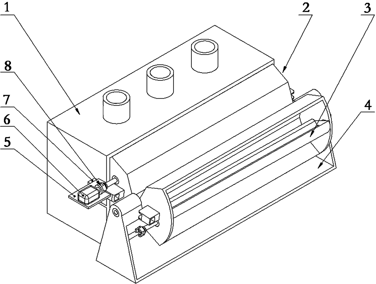
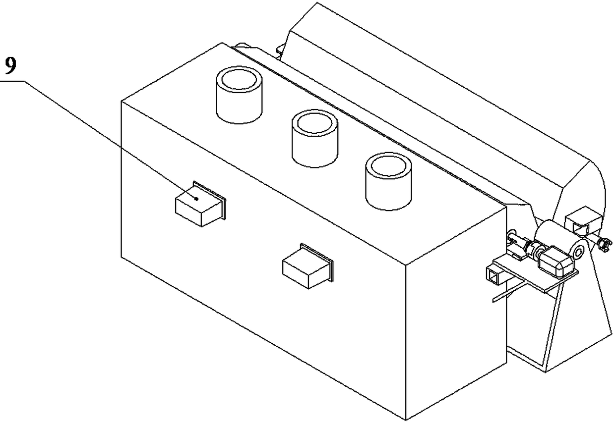
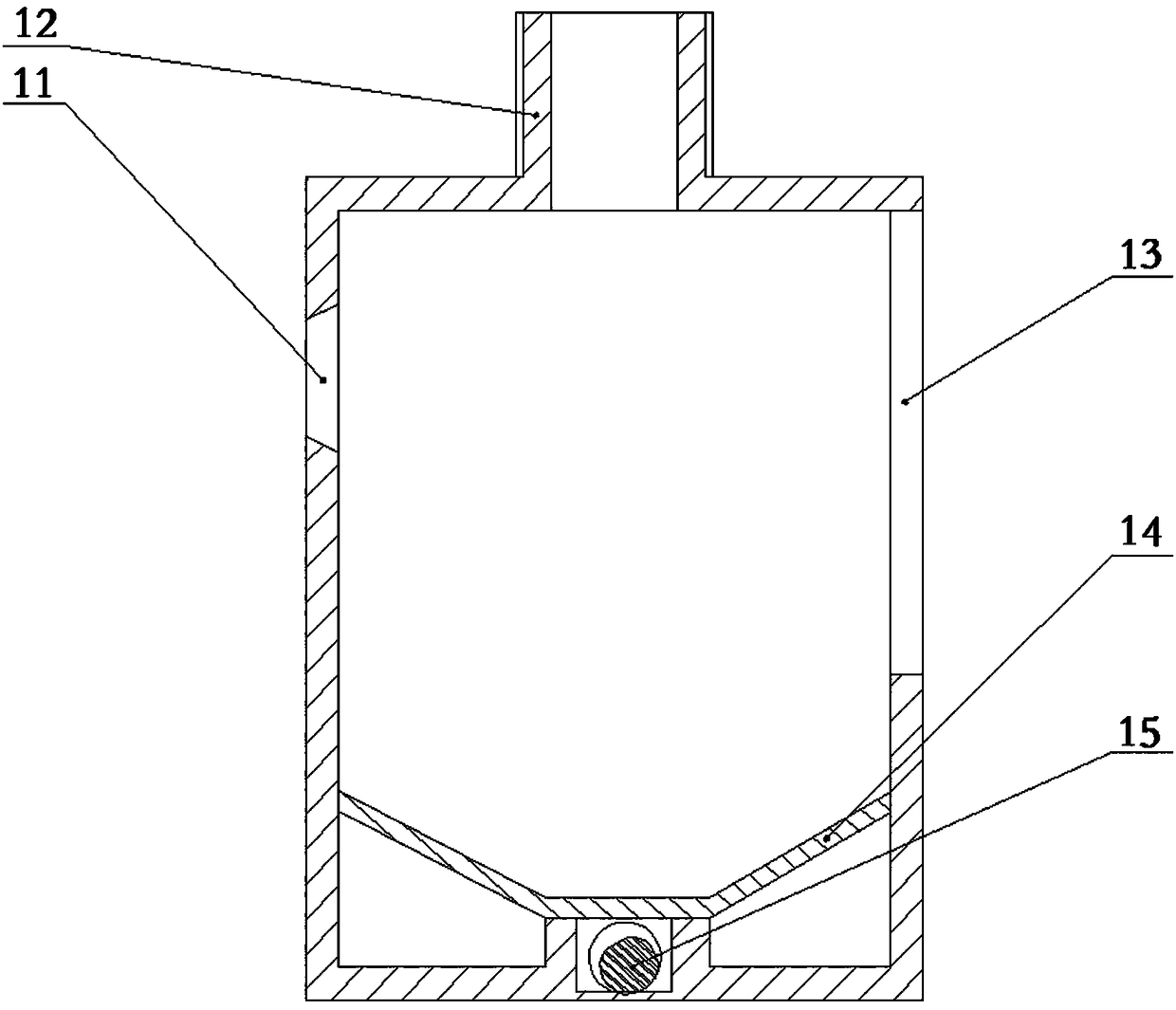
[0044] For the shot blasting machine, its inherent configuration must include the shot blasting chamber 1 and the shot blasting device 9. In some implementations, a shot recovery device can be selected, such as image 3 The floor drain plate 14 and the screw conveying device 15 are shown.

[0045] For different workpieces, in some applications, a feeding device needs to be provided, while in other applications, only workpiece tooling needs to be installed in the shot blasting chamber 1 .

[0046] For the coil wire, as described in the background technology section, there are relatively many feeding methods, but in the embodiment of the present invention, the hanging rod assembly 3 in the hopper assembly is used to hang the material in the shot blasting chamber 1 The position of the workpiece is determined, and the coiled wire is dispersed by throwing the coiled wire through the cam 34 .

[0047] Further, see the attached figure 1 A kind of flipping coil wire rod shot blastin...


PUM


Abstract

The invention discloses a turnover type shot blasting machine for a coil wire. The turnover type shot blasting machine comprises a shot blasting chamber, a shot blasting device, a turnover device anda driving device. The turnover device is arranged on the door side of the shot blasting chamber, the turnover device is provided with a turnover shaft parallel to the reference axial direction, and aturnover frame is installed on the turnover shaft. A first hopper assembly is installed on the turnover frame and located on one side of the turnover shaft, a second hopper assembly is installed on the turnover frame and located on the other side of the turnover shaft, one of the first hopper assembly and the second hopper assembly is located inside a door, the other of the first hopper assembly and the second hopper assembly is located outside the door, and the positions of the first hopper assembly and the second hopper assembly can be interchanged based on turnover. The first hopper assembly and the second hopper assembly each is provided with a set of hanger rod assemblies, the hanger rod assemblies are provided with seat parts and cams which are installed on the seat parts, and the cams are used for hanging the coil wire. The driving device is used for driving the cams to rotate. According to the turnover type shot blasting machine for the coil wire, the coil wire is easier to disperse.

Description

technical field [0001] The invention relates to a flipping coil wire shot blasting machine. Background technique [0002] There are two main types of wires, one is wires that cannot form coils, such as steel bars, and the other is wires that can be coiled into coils, such as steel wire ropes. For the former, the optional feeding method is relatively simple. , can only feed in a straight line, and for the latter, you can choose to feed in coils or after stretching. For the coiled wire, the two feeding methods have their own advantages and disadvantages. For the linear feeding after the coiled wire is unrolled, it needs to provide at least a supply end reel and a discharge end reel, and the wire needs to be tensioned. The machine takes up a lot of space. The key problem is that the diameter of the wire is relatively small, and the jet flow of the shot blaster is a conical jet flow from the exit of the shot blaster to the small end. In general, most of the projectiles are fi...

Claims


Application Information

Patent Timeline
IPC IPC(8): B24C3/32B24C9/00
CPCB24C3/32B24C9/00B24C9/003
Inventor 颜新宇王守仁王勇刘文涛陈素素薛传艺张晓东李登蓬
Owner UNIV OF JINAN
Why Eureka
Try Eureka