
Photovoltaic panel fault positioning method based on unmanned aerial vehicle (UAV) and thermal imaging technology

A thermal imaging technology and fault location technology, applied in the field of photovoltaic power generation, can solve problems such as temperature rise at the fault location, large footprint of photovoltaic modules, time-consuming, labor-intensive and low efficiency

Inactive Publication Date: 2018-08-10
TONGJI UNIV +3
View PDF3 Cites 30 Cited by
  • Summary
  • Abstract
  • Description
  • Claims
  • Application Information

AI Technical Summary

Problems solved by technology

[0004] The traditional fault detection method mainly judges whether there is a fault in the photovoltaic module by detecting the power generated by the photovoltaic module. However, although this method can judge whether there are faults such as dust blocking and hot spots, it is difficult to accurately detect the occurrence of faults in a huge number of photovoltaic panels. Locating the fault
[0005] After a hot spot fault occurs on a photovoltaic panel, the temperature of the fault location will rise. Therefore, the thermal imaging of the photovoltaic panel is performed by an infrared camera, and the fault location can be judged from the temperature distribution in the infrared image. Hand-held testing equipment is used for troubleshooting, but photovoltaic modules often occupy a huge area. Manual fault inspection and location of photovoltaic modules is time-consuming, labor-intensive and inefficient, and cannot meet actual needs.

Method used


Image

  • Photovoltaic panel fault positioning method based on unmanned aerial vehicle (UAV) and thermal imaging technology
  • Photovoltaic panel fault positioning method based on unmanned aerial vehicle (UAV) and thermal imaging technology
  • Photovoltaic panel fault positioning method based on unmanned aerial vehicle (UAV) and thermal imaging technology

Examples


Embodiment Construction

[0039] The preferred embodiments of the present invention are described in detail below, so that the advantages and features of the present invention can be more easily understood by those skilled in the art, so as to define the protection scope of the present invention more clearly.

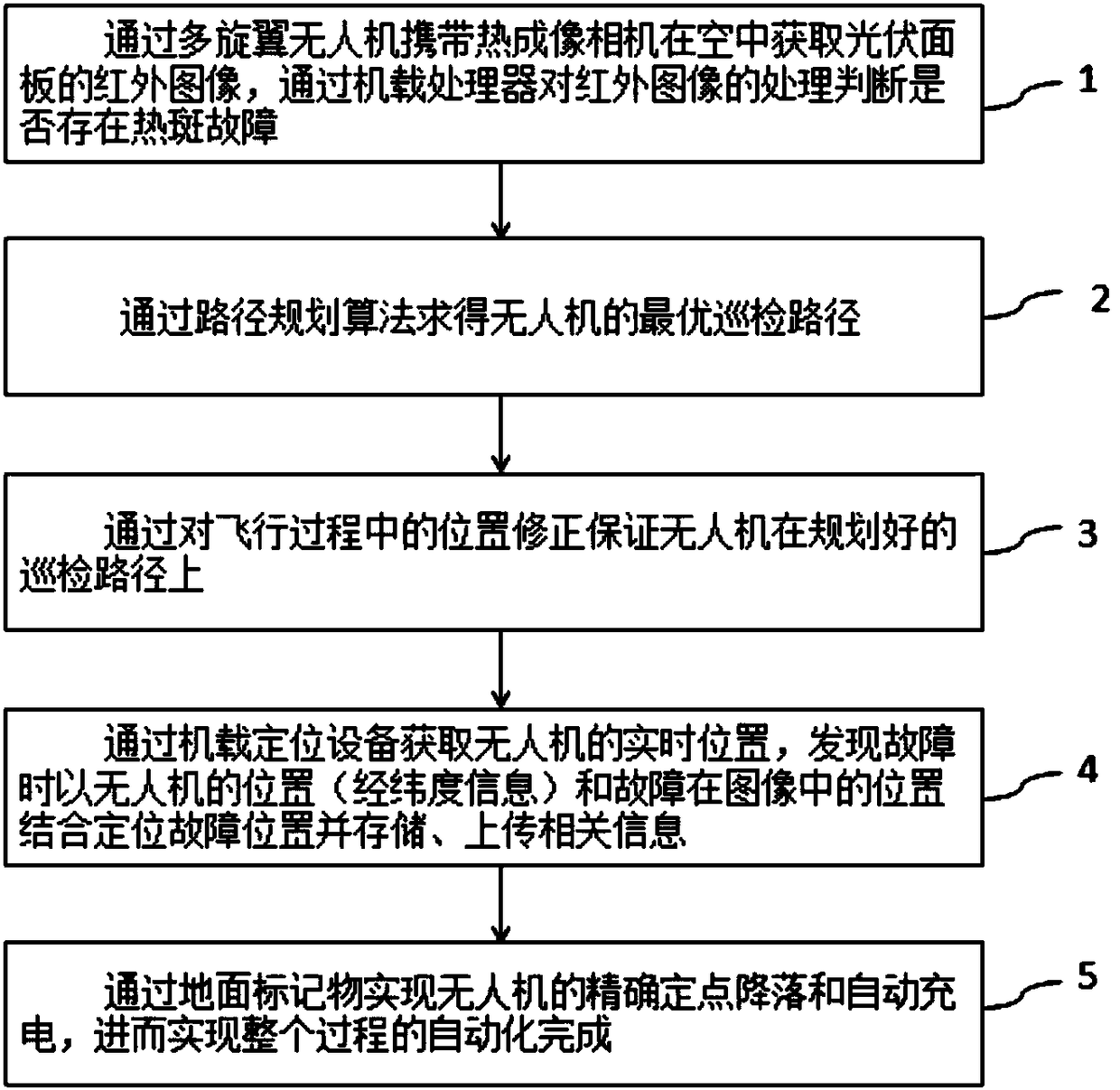
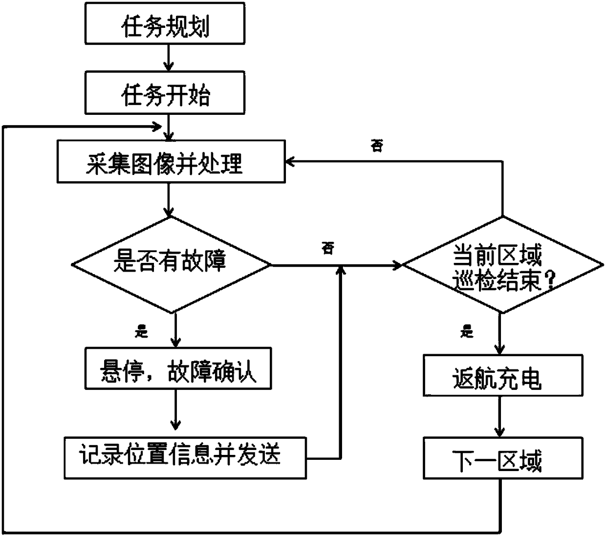
[0040] A photovoltaic panel fault location method based on UAV and thermal imaging technology, which can automatically and efficiently realize the fault detection of photovoltaic modules in photovoltaic power plants. The process is as follows figure 1 As shown, it specifically includes the following steps:

[0041] Step 1. Obtain the infrared image of the photovoltaic panel in the air through the thermal imaging camera carried by the multi-rotor UAV, and judge whether there is a hot spot fault through the processing of the infrared image by the onboard processor;

[0042] Step 2. Obtain the optimal inspection path of the UAV through the path planning algorithm, and ensure that the UAV is on the ...


PUM


Abstract

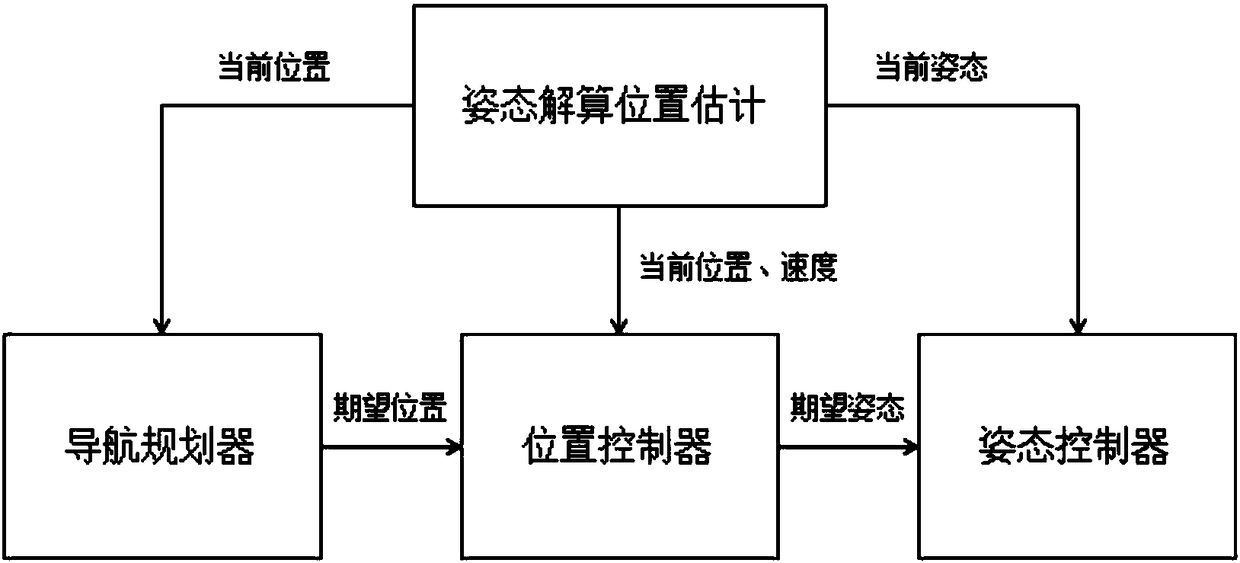
The invention discloses a photovoltaic panel fault positioning method based on an unmanned aerial vehicle (UAV) and a thermal imaging technology. The method includes the following steps: adopting a thermal imaging camera carried by a multi-rotor UAV to obtain an infrared image of a photovoltaic panel in the air, and adopting an onboard processor to process the infrared image and judge whether theinfrared image has a hot spot fault; calculating an optimal inspection path of the UAV, and ensuring that the UAV is on a planned inspection path by correcting the location during the flight; acquiring the real-time location of the UAV through onboard positioning equipment, and when the fault is found, combining the location of the UAV (latitude and longitude information) and the location of the fault in the image to position the fault location, and storing and uploading relevant information; and implementing precise spot landing and automatic charging of the UAV through a ground marker, and further achieving the automation of the whole process. According to the photovoltaic panel fault positioning method disclosed by the invention, the fault detection and positioning of the photovoltaic panel can be performed intelligently and efficiently, and the purpose of operation and maintenance of a photovoltaic power station can be achieved.

Description

technical field [0001] The invention belongs to the technical field of photovoltaic power generation, and specifically relates to the power generation efficiency of a photovoltaic power station and the overall operation and maintenance technology of a photovoltaic power station, in particular to a photovoltaic panel fault location method based on drones and thermal imaging technology. Background technique [0002] In order to alleviate the shortage of energy resources and the impact of climate change, countries around the world are gradually increasing the development and investment in the field of renewable energy. Due to its universality of resources, safety, reliability and noise-free characteristics, photovoltaic power generation has become a renewable energy that countries are competing to develop after wind power. Renewable energy power generation plays an important role in the long-term energy strategy. As of the end of 2016, the cumulative installed capacity of photo...

Claims


Application Information

Patent Timeline
IPC IPC(8): H02S50/15G05D1/10
CPCG05D1/101H02S50/15Y02E10/50
Inventor 沈润杰马明何斌汪宁渤吕清泉马彦宏张健美路肖肖王超张建卜王腾科李昆明
Owner TONGJI UNIV
Learn More