Magnetic force constraint piston type stable flow valve

A steady flow valve and piston type technology, which is applied in safety valves, balance valves, valve devices, etc., can solve the problems of high cost, high maintenance cost of single pump and double pump circuit steady flow valves, complex structure of steady flow valves, etc. To achieve the effect of simplified structure and simple structure

Active Publication Date: 2018-08-07
SHANGHAI RES INST OF CHEM IND
View PDF7 Cites 0 Cited by
  • Summary
  • Abstract
  • Description
  • Claims
  • Application Information

AI Technical Summary

Problems solved by technology

[0003] However, these existing steady flow valves have complex structures, high costs, and can only feedback the flow changes at the input or output ends.
The spring gasket of the single-channel constant flow valve is prone to aging and failure, and the maintenance cost of the single-pump and double-pump constant-flow valves is relatively high

Method used


Image

  • Magnetic force constraint piston type stable flow valve
  • Magnetic force constraint piston type stable flow valve

Examples


Embodiment 1

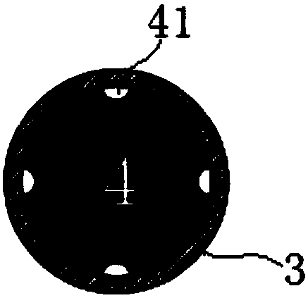
[0037] A magnetically restrained piston type steady flow valve, such as figure 1 As shown, it includes a valve body 3, a proximal gas end pipe section 1, an end cap 8, a piston 4 and a magnet 5: wherein, the proximal gas end pipe section 1 is connected to one end of the valve body 3 through a PTFE sealing plug 2; the end capping 8 It is arranged at the other end of the valve body 3, and is provided with a fluid through hole 81; the piston 4 is arranged in the valve body 3, and the end face facing the sealing end 8 is provided with a conical body 7 that matches the fluid through hole 81; and the piston 4 It has an inner iron core 6, and the magnet 5 is sleeved outside the valve body 3, and can move along the length direction of the valve body 3 (moving direction such as figure 1 shown by the double arrows).

[0038] In this embodiment, the valve body 3 is made of glass material for easy observation, the proximal gas end pipe section 1 is also made of glass material, the piston...


PUM


Abstract

The invention relates to a magnetic force constraint piston type stable flow valve which comprises a valve body, a close-gas end pipe section, a sealing end, a piston and a magnetic body. The close-gas end pipe section is connected to one end of the valve body through a Teflon sealing plug, the sealing end is arranged at the other end of the valve body, and a fluid through hole is formed; and thepiston is arranged in the valve body, the end face facing the sealing end is provided with a taper body matched with the fluid through hole, the piston is provided with an inner iron core, and the magnetic body is arranged outside the valve body in a sleeving manner and can move in the length direction of the valve body. Compared with the prior art, the magnetic force constraint piston type stableflow valve is simple and reliable in structure, low in failure rate and easy to detach and wash, the taper body and the fluid through hole in the sealing end form a flow negative feedback structure,and response to the flow changes of the input end and the output end can be achieved.

Description

technical field [0001] The invention belongs to the field of steady flow valve devices, in particular to a magnetic force restraint piston type steady flow valve. Background technique [0002] In fluid control processes, steady flow devices are widely used to overcome fluid flow fluctuations. Its working principle is to control the flow of the valve to be stable and constant through negative feedback on the upstream flow of the valve body. At present, the widely used steady flow valves include single-pump single-circuit steady-flow diverter valve, single-circuit constant-flow valve and dual-pump single-circuit steady-flow diverter valve. The single-pump single-channel steady flow diverter valve is actually composed of a fixed differential pressure reducing valve and a fixed orifice. After the high-pressure fluid enters the valve, it is divided into two channels, and one channel enters the working system through the variable orifice A (no steady flow is required), The other...

Claims


Application Information

Patent Timeline
IPC IPC(8): F16K17/28
CPCF16K17/28
Inventor 冷远鹏张小沁章明洪段路路
Owner SHANGHAI RES INST OF CHEM IND
Why Eureka
Try Eureka