An oil distribution valve with unloading function

A technology of oil circuit distribution and function, applied in the direction of servo motors, servo motor components, mechanical equipment, etc., can solve problems such as no unloading function, excessive decline of actuators, increased cost of electronic control and system complexity, etc.

Active Publication Date: 2019-12-24
江苏南京国家农业高新技术产业示范区发展集团有限公司
View PDF6 Cites 0 Cited by
  • Summary
  • Abstract
  • Description
  • Claims
  • Application Information

AI Technical Summary

Problems solved by technology

The disadvantages in the existing oil circuit are: (1) the price of each electro-hydraulic proportional multi-way valve is expensive, the market price is 3000-4000 yuan, and there is cost pressure for mechanical equipment with low price; Each electro-hydraulic proportional valve must be equipped with an amplifier or controller, and the selection of multiple electro-hydraulic proportional valves also increases the cost of electronic control and the complexity of the system
[0003] In order to solve the above problems, circuit selection valves have appeared on the existing market, such as Figure 4 As shown, only one piece of electro-hydraulic proportional valve can be used in the hydraulic circuit, and which oil cylinder to control is selected through the control of the circuit selection valve. The existing circuit selection valve can well replace the expensive electro-hydraulic proportional valve and reduce the electric The cost of the control system; but this circuit selection valve cannot be used in a hydraulic circuit containing a hydraulic lock or a balance valve, because the four working oil ports of the existing circuit selection valve are in a cut-off state when they are in a non-working state, and do not have The unloading function will cause the delayed closing of the hydraulic lock and the balance valve, which will cause the excessive slide of the actuator

Method used


Image

  • An oil distribution valve with unloading function
  • An oil distribution valve with unloading function
  • An oil distribution valve with unloading function

Examples


Embodiment Construction

[0023] Embodiments of the present invention are described in detail below, examples of which are shown in the drawings, wherein the same or similar reference numerals designate the same or similar elements or elements having the same or similar functions throughout. The embodiments described below by referring to the figures are exemplary and are intended to explain the present invention and should not be construed as limiting the present invention.

[0024] An oil distribution valve with an unloading function according to an embodiment of the present invention will be described in detail below with reference to the accompanying drawings.

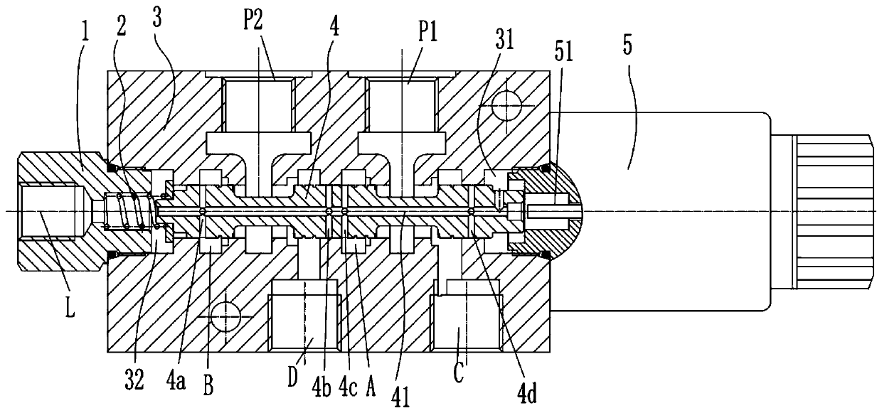
[0025] An oil distribution valve with an unloading function according to an embodiment of the present invention includes: a valve body 3 , a valve core 4 , a left end cover 1 , an elastic member 2 , and an electromagnet 5 .

[0026] Specifically, the valve body 3 has a valve hole penetrating the valve body 3 in the left-right direction, the...


PUM


Abstract

The invention provides an oil line distribution valve with an unloading function. The oil line distribution valve is characterized in that a valve hole is formed in a valve body; the valve hole is provided with a left pressure relief cavity and a right pressure relief cavity; the valve body is provided with a first oil port, a second oil port, a third oil port, a fourth oil port, a fifth oil portand a sixth oil port; a valve core is movably arranged in the valve hole left and right; a flow through hole, a first pressure relief hole, a second pressure relief hole, a third pressure relief holeand a fourth pressure relief hole are formed in the valve core; a left end cover is detachably arranged on the valve body to seal the left end of the valve hole, and is provided with a seventh oil port; the left end of an elastic part is abutted against the right end of the left end cover, and the right end of the elastic part is abutted against the left end of the valve core; an electromagnet isdetachably arranged on the valve body to seal the right end of the valve hole, and a push rod of the electromagnet is moved left, and is aligned with the right end of the valve core. The oil line distribution valve with the unloading function provided by the embodiment has the advantages that the structure is simple, the cost is low, and the installation is convenient.

Description

technical field [0001] The invention relates to a valve, in particular to an oil distribution valve with an unloading function. Background technique [0002] In modern industrial hydraulic and mobile machinery hydraulic oil circuits, a large number of identical actuators (hydraulic cylinders or hydraulic motors) are used in parallel and sequentially acting oil circuits. Such as Figure 5 As shown, in the existing hydraulic system, the corresponding number of electro-hydraulic proportional multi-way valves is generally selected according to the number of actuators to control the actuators. The disadvantages in the existing oil circuit are: (1) the price of each electro-hydraulic proportional multi-way valve is expensive, the market price is 3,000-4,000 yuan, and there is cost pressure on mechanical equipment with low price; (2) Each electro-hydraulic proportional valve must be equipped with an amplifier or controller, and the selection of multiple electro-hydraulic proportio...

Claims


Application Information

Patent Timeline
Patent Type & Authority Patents(China)
IPC IPC(8): F15B13/06F15B11/16
CPCF15B11/16F15B13/06
Inventor 邵立坤
Owner 江苏南京国家农业高新技术产业示范区发展集团有限公司
Why Eureka
Try Eureka