Robot steering error calibration method, device and system
A technology of error calibration and robotics, applied in manipulators, manufacturing tools, etc., can solve problems such as angle errors, and achieve the effect of reducing angle errors
- Summary
- Abstract
- Description
- Claims
- Application Information
AI Technical Summary
Problems solved by technology
Method used
Image
Examples
specific Embodiment 1
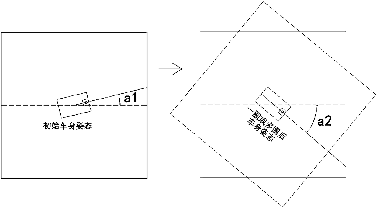
[0053] Such as Figure 1a and Figure 1b As shown, the embodiment of the present invention provides a robot steering error calibration method, including:
[0054] Fence setting step S101, setting a rectangular fence;
[0055] Initial attitude acquisition step S102, after the robot drives into the fence, scan the environment through the laser radar installed on the robot, monitor the four sidelines of the fence, and obtain the initial attitude angle a1 of the robot relative to the fence;
[0056] Turn step S103 to control the robot to turn the angle p in situ;
[0057] The current attitude acquisition step S104 is to scan the environment through the laser radar, monitor the four sidelines of the fence, and obtain the current attitude angle a2 of the robot relative to the fence;
[0058] The steering error calculation step S105 is to calculate the steering error m of the robot according to the initial attitude angle a1, the current attitude angle a2 and the rotation angle p: ...
specific Embodiment 2
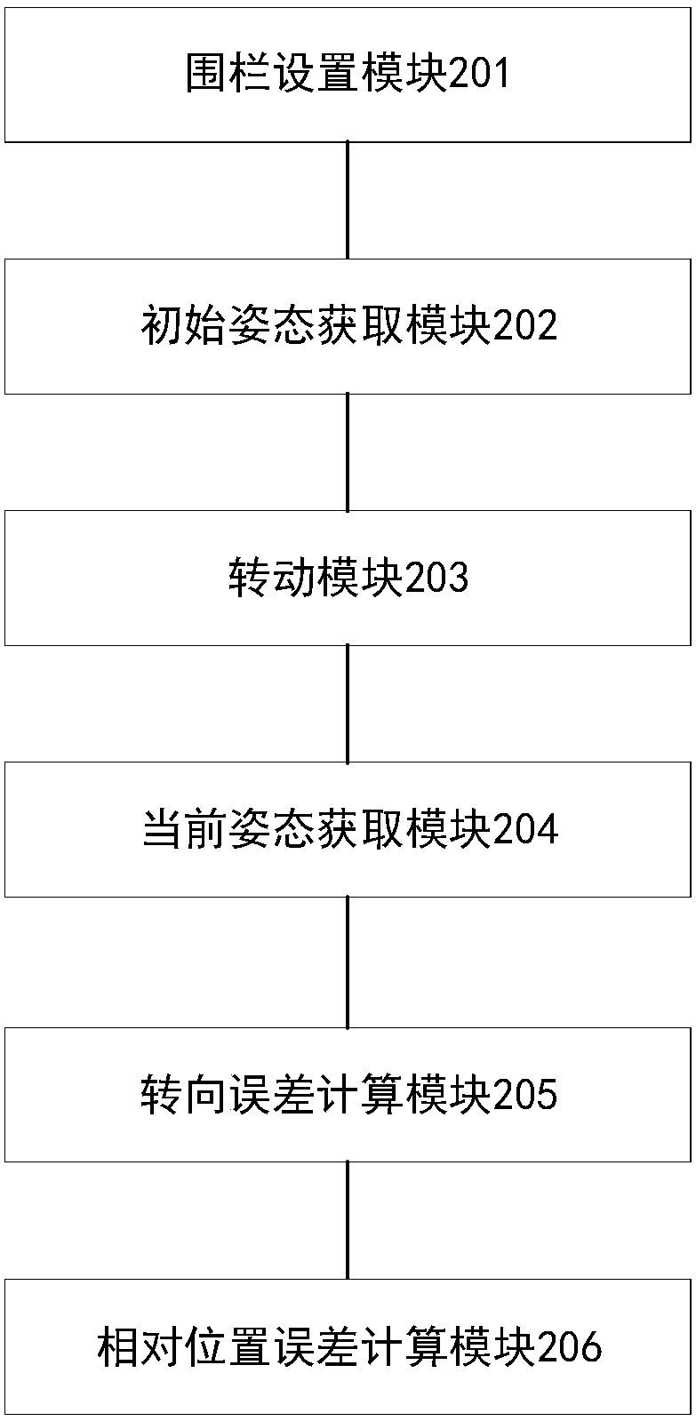
[0068] Such as figure 2 As shown, the embodiment of the present invention provides a robot steering error calibration device, including:
[0069] The fence setting module 201 is used to set a rectangular fence;
[0070] The initial attitude acquisition module 202 is used to scan the environment through the laser radar installed on the robot after the robot enters the fence, monitor the four sidelines of the fence, and obtain the initial attitude angle a1 of the robot relative to the fence;
[0071] The rotation module 203 is used to control the rotation angle p of the robot in situ;
[0072] The current attitude acquisition module 204 is used to scan the environment by laser radar, monitor the four sidelines of the fence, and obtain the current attitude angle a2 of the robot relative to the fence;
[0073] The steering error calculation module 205 is used to calculate the steering error m of the robot according to the initial attitude angle a1, the current attitude angle a2...
specific Embodiment 3
[0080] Such as image 3 As shown, the embodiment of the present invention provides a robot steering error calibration system, including:
[0081] The robot steering error calibration device 301 in the second embodiment;
[0082] The fence 302 is used to provide a calibration site;
[0083] The laser radar 303 is installed on the robot, and the laser radar is used to scan the environment and monitor the 4 sidelines of the fence.
[0084] The embodiment of the present invention can calculate the relative position error of the left wheel and the right wheel of the robot according to the steering error, and calibrate the relative position error of the wheels, which can be compensated for the error during the subsequent movement of the robot, thereby reducing the turning of the robot Angle error during movement.
PUM
 Abstract
Description
Claims
Application Information
 - R&D
- Intellectual Property
- Life Sciences
- Materials
- Tech Scout
- Unparalleled Data Quality
- Higher Quality Content
- 60% Fewer Hallucinations
Browse by: Latest US Patents, China's latest patents, Technical Efficacy Thesaurus, Application Domain, Technology Topic, Popular Technical Reports.
© 2025 PatSnap. All rights reserved.Legal|Privacy policy|Modern Slavery Act Transparency Statement|Sitemap|About US| Contact US: help@patsnap.com


