Hydro-generator temperature control system used for hydroelectric power generation

A technology of temperature control system and water conservancy power generation, applied in the direction of temperature control, control/regulation system, non-electric variable control, etc., can solve the problems of difficult realization of process and hidden danger of safe operation of generators

Inactive Publication Date: 2018-08-03
赵静
View PDF4 Cites 0 Cited by
  • Summary
  • Abstract
  • Description
  • Claims
  • Application Information

AI Technical Summary

Problems solved by technology

[0004] Aiming at the deficiencies in the prior art, the purpose of the present invention is to provide a temperature control system for hydroelectric generators used in hydroelectric power generation, to solve the problem that temperature measuring resistors are usually buried in the iron core of the stator in the prior art, and through these temperature measuring resistors Connected with monitoring equipment, the stator temperature can be monitored in real time, but since the rotor of the hydroelectric generator is a rotating part, if temperature measuring resistors are embedded everywhere in the rotor, it is necessary to install many brushes to lead out the signal, which will inevitably affect the power generation. The safe operation of the machine brings hidden dangers, and it is difficult to realize the problem in the process

Method used


Image

  • Hydro-generator temperature control system used for hydroelectric power generation
  • Hydro-generator temperature control system used for hydroelectric power generation
  • Hydro-generator temperature control system used for hydroelectric power generation

Examples


Embodiment 1

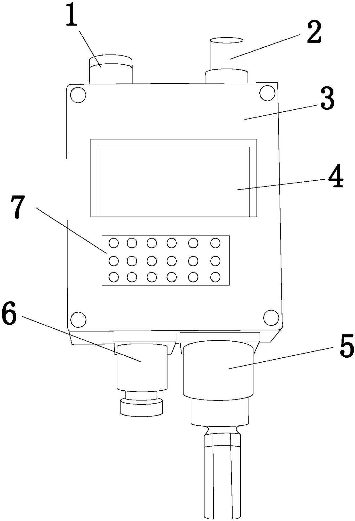
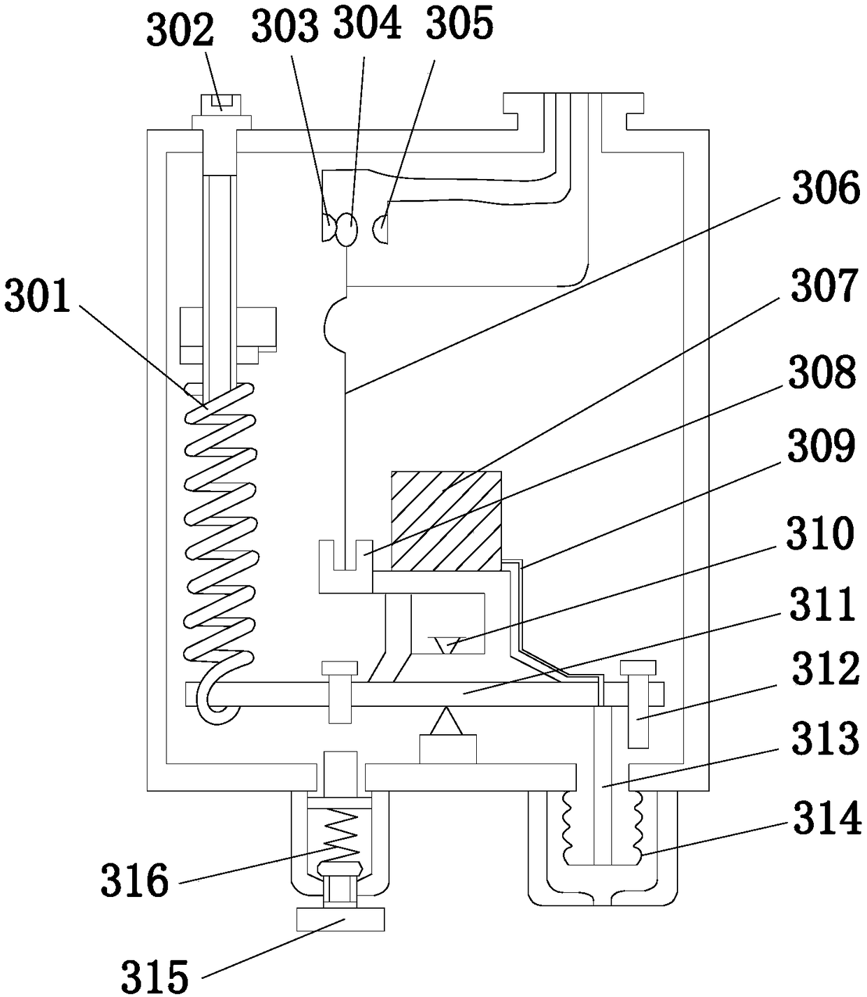
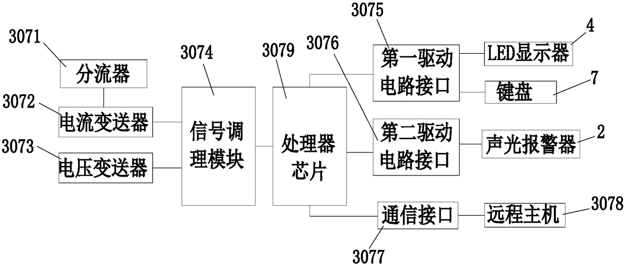
[0026] see Figure 1-Figure 5 , the present invention provides a temperature control system for hydraulic generators for hydraulic power generation, the structure of which includes an adjusting shaft 1, an audible and visual alarm 2, a temperature controller 3, an LED display 4, a bellows casing 5, and a differential spring sleeve 6 , a keyboard 7, an LED display 4 is installed at half of the front end of the temperature controller 3, the signal end of the LED display 4 is electrically connected to the signal of the keyboard 7, and the keyboard 7 and the LED display 4 are located at the same On the plane, the adjusting shaft 1 and the sound and light alarm 2 are fixedly installed on the upper port of the temperature controller 3, and the bellows shell 5 and the differential spring sleeve 6 are mechanically connected to the lower port of the temperature controller 3, so The inside of the temperature controller 3 includes a main spring 301, an adjusting rod 302, a scale 303, a s...

Embodiment 2

[0029] see Figure 1-Figure 6 , the voltage transmitter 3073 is composed of a rear cover 30731, a terminal block 30732, a circuit board 30733, a diaphragm 30734, a sealing ring 30735, a process connector 30736, and an adjustment potentiometer 30737. The inside of the rear cover 30731 is provided with wiring Terminal 30732 and circuit board 30733, the adjustment potentiometer 30737 is welded on the circuit board 30733 and electrically connected to the terminal 30732, the bottom of the circuit board 30733 is provided with a diaphragm 30734, and the diaphragm 30734 is connected to the process connector 30736 A sealing ring 30735 is installed at the joint.

[0030] The model of the voltage transmitter 3073 is SWP-T20 series. In order to improve the accuracy of temperature control, the voltage transmitter 3073 has strong anti-overload and impact resistance, high stability, and high measurement accuracy. Accuracy; its working principle is: the pressure of the measured medium direct...


PUM


Abstract

The invention discloses a hydro-generator temperature control system used for hydroelectric power generation. The structure of the system comprises an adjusting rotation shaft, an acousto-optic alarm,a temperature controller, an LED display, a bellows casing, an amplitude difference spring sleeve and a keyboard. According to the invention, an indirect method is used to measure the temperature ofthe rotor of a generator; a shunt, a current transducer and a voltage transducer are arranged to measure the temperature of the rotor of the generator; the measured current and voltage values pass through the temperature controller, and the measured temperature is transmitted to a processor for analysis and calculation; the temperature of the generator is controlled; embedding temperature measuring resistors in the whole rotor is avoided; the hidden danger of the safe operation of the generator is effectively avoided; the system has the advantages of simple operation and high practicability; the temperature controller can carry out remote communication to realize real-time monitoring of the temperature control of the generator; and the service life of the generator is effectively improved.

Description

technical field [0001] The invention relates to a water conservancy generator temperature control system for hydropower generation, which belongs to the field of hydraulic generator temperature control equipment. Background technique [0002] Water energy is an inexhaustible, renewable and clean energy. However, in order to effectively utilize natural water energy, it is necessary to artificially build hydraulic structures that can concentrate water flow and adjust flow, such as dams, diversion Water pipes and culverts, etc., so the project investment is large and the construction period is long, but the hydropower generation efficiency is high, the power generation cost is low, the unit starts quickly, and the adjustment is easy. Hydropower generation uses rivers, lakes, etc. The contained potential energy is converted into the kinetic energy of the water turbine, and then the water turbine is used as the driving force to drive the generator to generate electric energy, and...

Claims


Application Information

Patent Timeline
Patent Type & Authority Applications(China)
IPC IPC(8): G05D23/24
CPCG05D23/24
Inventor 毛杰赵文娟高星星刘德志徐探
Owner 赵静
Why Eureka
Try Eureka