Liquid crystal display device

A technology of a liquid crystal display device and a liquid crystal layer, applied in the direction of nonlinear optics, instruments, optics, etc., can solve the problems of affecting the display effect of the liquid crystal display device, light leakage, low precision, etc., and achieve enhanced display effect, high light transmittance, simplified structure effect

Inactive Publication Date: 2018-08-03
SHENZHEN CHINA STAR OPTOELECTRONICS TECH CO LTD
View PDF14 Cites 5 Cited by
  • Summary
  • Abstract
  • Description
  • Claims
  • Application Information

AI Technical Summary

Problems solved by technology

However, using the black matrix to shield light not only requires a separate photomask and manufacturing process, but also due to the low precision of the manufacturing dimensions of the black matrix, light leakage is often caused by lamination deviation, which greatly affects the liquid crystal display device. The display effect of

Method used


Image

  • Liquid crystal display device
  • Liquid crystal display device
  • Liquid crystal display device

Examples


Embodiment Construction

[0022] The following will clearly and completely describe the technical solutions in the embodiments of the present invention. Obviously, the described embodiments are only some of the embodiments of the present invention, rather than all the embodiments. Based on the embodiments of the present invention, all other embodiments obtained by persons of ordinary skill in the art without making creative efforts belong to the protection scope of the present invention.

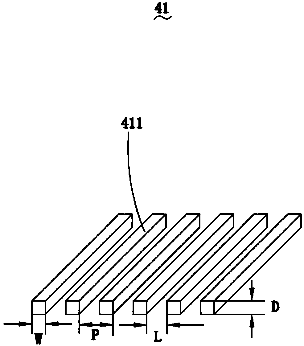
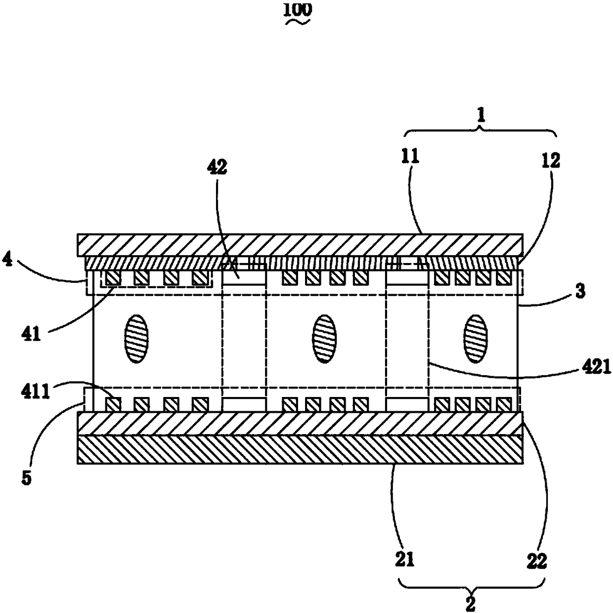
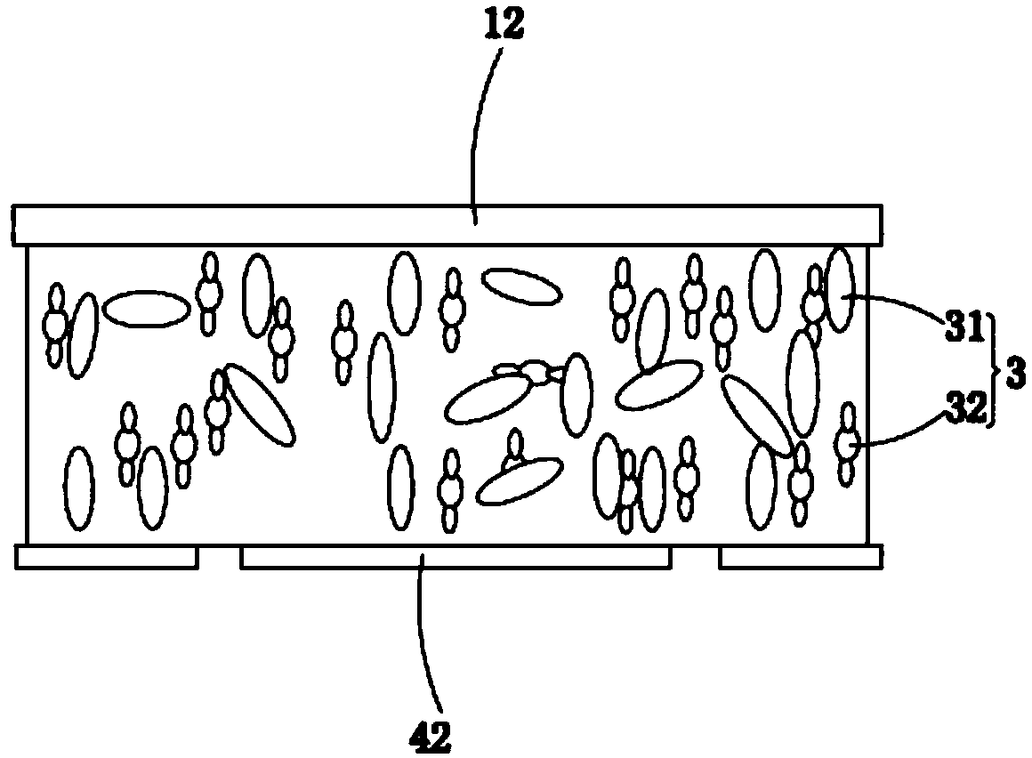
[0023] Please also see figure 1 and figure 2 ,in, figure 1 It is a structural schematic diagram of the polarizing unit of the liquid crystal display device of the present invention; figure 2 It is a structural schematic diagram of the liquid crystal display device of the present invention. The present invention provides a liquid crystal display device 100, which includes an upper substrate 1, a lower substrate 2, a liquid crystal layer 3 sandwiched between the upper substrate 1 and the lower substrate 2, a first...


PUM

PropertyMeasurementUnit
widthaaaaaaaaaa
thicknessaaaaaaaaaa

Abstract

The invention provides a liquid crystal display device. The device comprises an upper substrate, a lower substrate, a liquid crystal layer clamped between the upper substrate and the lower substrate and first and second wire grid layers which are oppositely arranged at intervals; the upper substrate comprises a first substrate base and a color filter overlaid on the side, close to the liquid crystal layer, of the first substrate base, and the first wire grid layer is clamped between the liquid crystal layer and the color filter; the lower substrate comprises a second substrate base and a TFT layer overlaid on the side, close to the liquid crystal layer, of the second substrate base, and the second wire grid layer is clamped between the liquid crystal layer and the TFT layer; the first andsecond wire grid layers comprise polarizer units and light blocking units, and the light blocking units are inserted between the adjacent two polarizer units. Compared with the prior art, the liquid crystal display device has high display precision and low production cost.

Description

technical field [0001] The invention relates to the field of liquid crystal display devices, in particular to a liquid crystal display device adopting a metal wire grid layer structure. Background technique [0002] A liquid crystal display device in the related art includes a backlight, an upper polarizer, a lower polarizer, a liquid crystal layer sandwiched between the upper polarizer and the lower polarizer, and a liquid crystal layer sandwiched between the upper polarizer and the liquid crystal layer. The color filter in between and the TFT layer interposed between the liquid crystal layer and the lower polarizer, the backlight source is arranged on the side of the lower polarizer away from the liquid crystal layer. [0003] The working principle of the liquid crystal display device is to use the birefringence property of the liquid crystal to control the rotation of the liquid crystal in the liquid crystal layer through the voltage, so that the linearly polarized light ...

Claims


Application Information

Patent Timeline
Patent Type & Authority Applications(China)
IPC IPC(8): G02F1/1335G02F1/1343
CPCG02F1/133512G02F1/133528G02F1/134309G02F1/13439G02F1/133548
Inventor 韦宏权
Owner SHENZHEN CHINA STAR OPTOELECTRONICS TECH CO LTD
Why Eureka
Try Eureka