Eureka AIR delivers breakthrough ideas for toughest innovation challenges, trusted by R&D personnel around the world.

Computer-implemented method for detecting a cornea vertex

A corneal vertex, computer technology, applied in computer parts, computing, eye testing equipment, etc., can solve problems such as image overlap, camera arrangement restrictions, etc.

Active Publication Date: 2018-08-03
CARL ZEISS VISION INT GMBH +1
View PDF6 Cites 0 Cited by
  • Summary
  • Abstract
  • Description
  • Claims
  • Application Information

AI Technical Summary

Problems solved by technology

Correspondingly, the premise is that the images mostly overlap, so the choice of camera arrangement is severely limited

Method used


Image

  • Computer-implemented method for detecting a cornea vertex
  • Computer-implemented method for detecting a cornea vertex
  • Computer-implemented method for detecting a cornea vertex

Examples


Embodiment approach

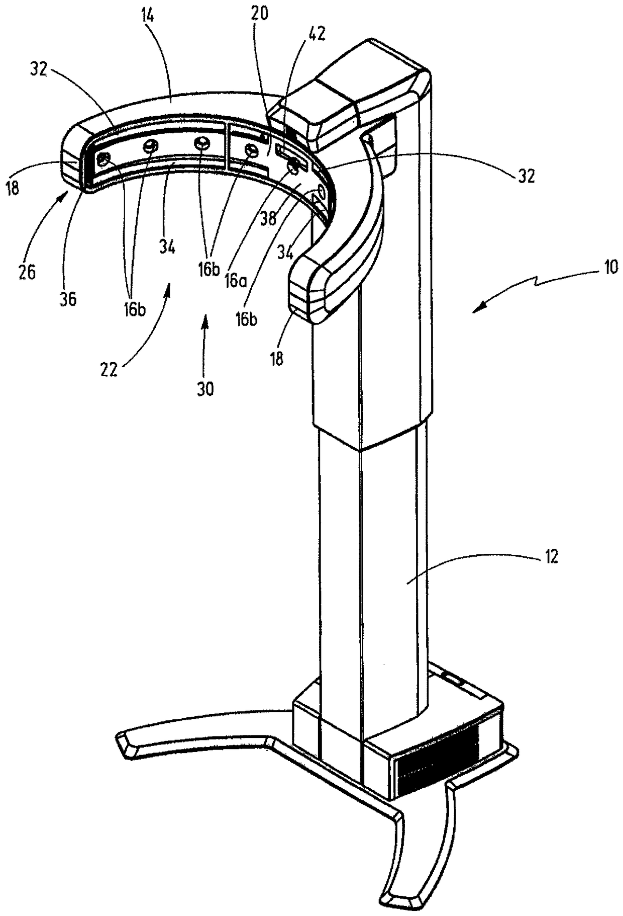
[0040] 1. A computer-implemented method for detecting the corneal apex, wherein a frontal image of the head and a lateral image of the head are provided, these images being calibrated to each other, wherein, from the frontal image and the The profile image determines the spatial position of the corneal apex.

[0041] 2. The computer-implemented method according to item 1, characterized in that triangulation is used in determining the geometric position.

[0042] 3. The computer-implemented method according to item 1 or 2, characterized in that the position of the corneal apex is corrected for calculation.

[0043] 4. The computer-implemented method according to one of the preceding items, characterized in that the position of the corneal apex in space is determined in a first approximation as an intersection point q, which is the side camera that captures the side image Intersection of a first line of sight ( 52 ) tangential to the cornea ( 50 ) of ( 16 b ) and a second line ...


PUM


Abstract

The invention relates to a computer-implemented method that detects the position of a corneal vertex from a frontal image of a head and a lateral image of the head. The front and lateral images are calibrated to one another, and the position of the corneal vertex in space is determined from the frontal image and the lateral image with a geometric position determination.

Description

technical field [0001] The invention relates to a computer-implemented method for detecting the corneal apex according to the preamble of claim 1, a computer-implemented method for detecting the corneal apex according to the preamble of claim 3 A method for detecting a corneal apex according to the preamble of claim 5, a computer-implemented method for detecting a corneal apex according to the preamble of claim 13 , and a computer-implemented method for detecting corneal vertices according to the preamble of claim 14. Background technique [0002] The apex of the subject's cornea is important in determining the centering parameters used to adjust the eyeglasses. The centering parameters are used to correctly arrange or center the spectacle lens in the spectacle frame so that the spectacle lens is arranged in the correct position relative to the eyes of the person wearing the spectacle. Here, sometimes it is an anatomical parameter of the person concerned (e.g. pupillary di...

Claims


Application Information

Patent Timeline
IPC IPC(8): A61B3/14G06K9/00
CPCA61B3/14G06V40/193A61B3/10A61B3/111G02C13/003G02C13/005A61B3/107G06T7/73G06T2207/30041A61B3/1005G01M11/0207G02C7/061G02C2202/22
Inventor C.妞文休斯O.施瓦茨M.甘珀林
Owner CARL ZEISS VISION INT GMBH
Why Eureka
Eureka Blog
Learn More