Water squeezing device suitable for rolling mop
A water squeezing device and mop technology, applied in the field of mops, can solve the problems of unfavorable popularization, affecting the use performance, inability to clean the drum for dehydration treatment, etc., and achieve the advantages of good washing effect, convenient force application, and improved convenience and comfort. Effect
- Summary
- Abstract
- Description
- Claims
- Application Information
AI Technical Summary
Problems solved by technology
Method used
Image

Examples
Embodiment 1
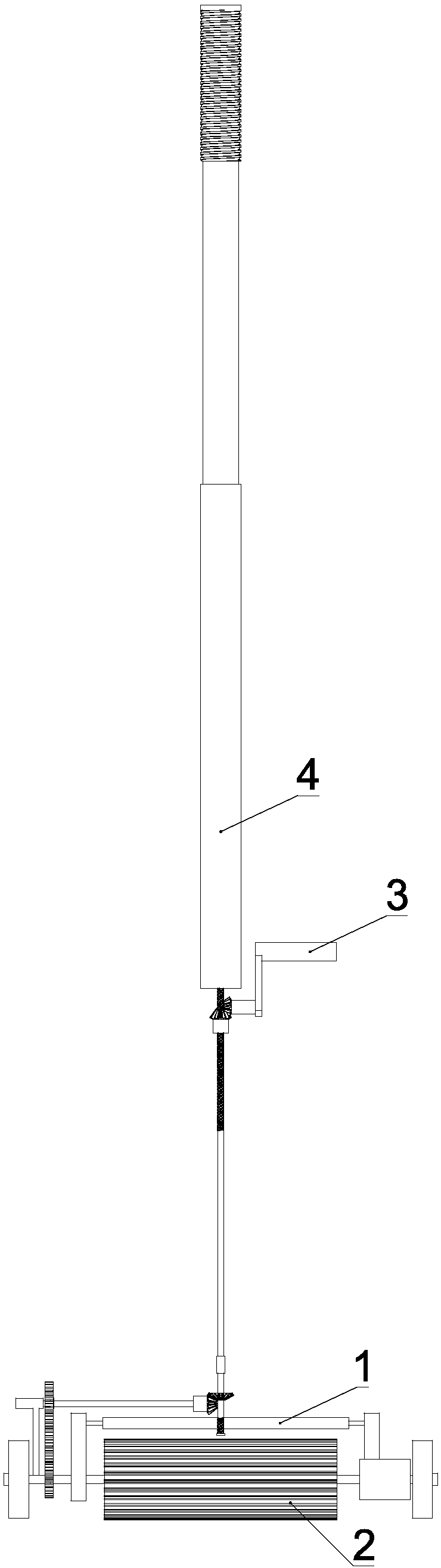
[0035] see figure 1 , a water squeezing device suitable for a rolling mop of the present invention includes a water squeezing part 1, a press switching mechanism for controlling the contact or separation of the water squeezing part 1 and the cleaning cylinder 2, a rocker 3, and a The rotating shafts of the rollers 2 are used for power transmission to drive the rocking and rotating mechanism of the cleaning roller 2, wherein the rocking handle 3 is arranged on the push rod 4 of the rolling mop.
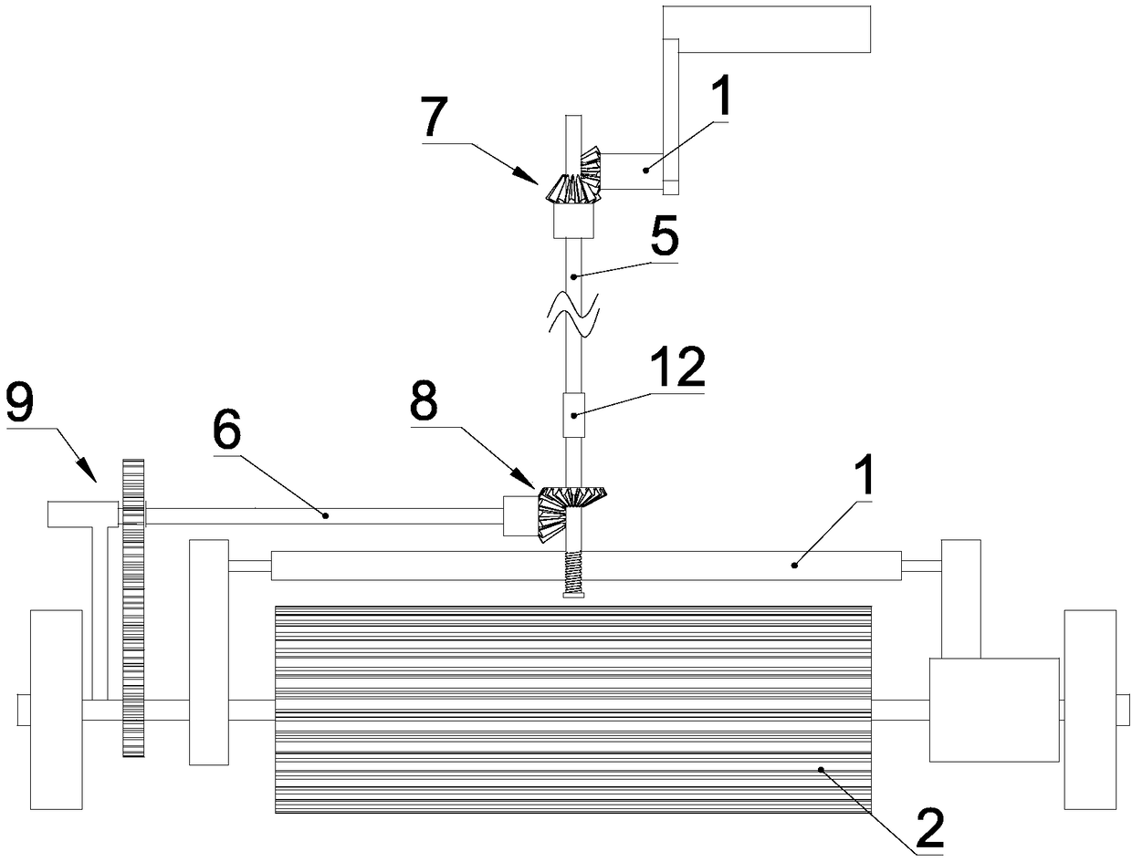
[0036] see figure 2 , the rocking and rotating mechanism is composed of a gear transmission mechanism, and the gear transmission mechanism includes a first transmission rod 5 vertically arranged in the inner cavity of the push rod 4 and a second transmission rod 5 horizontally arranged between the first transmission rod 5 and the cleaning roller 2 Two transmission rods 6, wherein, the crank handle 3 and the first transmission rod 5 are connected through the first bevel gear set 7, an...
Embodiment 2
[0046] see Figure 7 The difference between this embodiment and Embodiment 1 is that the rocking and rotating mechanism is composed of a conveyor belt mechanism group, and the conveyor belt mechanism group includes a first rotating shaft connected to the rocker 3 and is located between the first rotating shaft and the cleaning roller 2. The second rotating shaft, wherein, the first rotating shaft is provided with a first pulley 12, the rotating shaft of the cleaning roller 2 is provided with a second pulley 13, and the second rotating shaft cooperates with the first pulley 12 A third pulley 14 is provided on the ground, and the third pulley 14 is connected with the first pulley 12 through the first transmission belt, and the second rotating shaft is provided with a fourth pulley 15 in cooperation with the second pulley 13 , the fourth pulley 15 is connected with the second pulley through a second transfer belt. During work, the rocking handle 3 rotates to drive the first rota...
Embodiment 3
[0049] see Figure 8 and Figure 9 , The difference between this embodiment and Embodiment 1 is that the water squeezing member 1 is composed of a water squeezing roller 16 arranged on a fixed frame along the length direction of the cleaning roller 2, wherein, between the cleaning roller 2 and the fixed frame Turn to connect. During work, when the water squeezing cylinder 16 squeezes water to the cleaning cylinder 2 in rotation, itself also rotates synchronously with the cleaning cylinder 2, which can reduce the resistance of the cleaning cylinder 2 when rotating, and then in the same size Under the effect of the driving force, the rotation speed of the cleaning cylinder 2 is faster, so the dehydration effect is better.
[0050] In this embodiment, other implementation modes other than the above are implemented in Embodiment 1.
PUM
 Abstract
Description
Claims
Application Information
 - R&D
- Intellectual Property
- Life Sciences
- Materials
- Tech Scout
- Unparalleled Data Quality
- Higher Quality Content
- 60% Fewer Hallucinations
Browse by: Latest US Patents, China's latest patents, Technical Efficacy Thesaurus, Application Domain, Technology Topic, Popular Technical Reports.
© 2025 PatSnap. All rights reserved.Legal|Privacy policy|Modern Slavery Act Transparency Statement|Sitemap|About US| Contact US: help@patsnap.com