An immersion cooling system

A cooling system and coolant technology, applied in cooling/ventilation/heating transformation, data center, electrical components, etc., can solve health hazards and other problems

Inactive Publication Date: 2018-07-31
爱思欧托普集团有限公司
View PDF7 Cites 8 Cited by
  • Summary
  • Abstract
  • Description
  • Claims
  • Application Information

AI Technical Summary

Problems solved by technology

Exposure of users of cooling systems to even trace amounts of coolant breakdown products such as PFIB and HF may endanger their health

Method used


Image

  • An immersion cooling system
  • An immersion cooling system
  • An immersion cooling system

Examples


Embodiment Construction

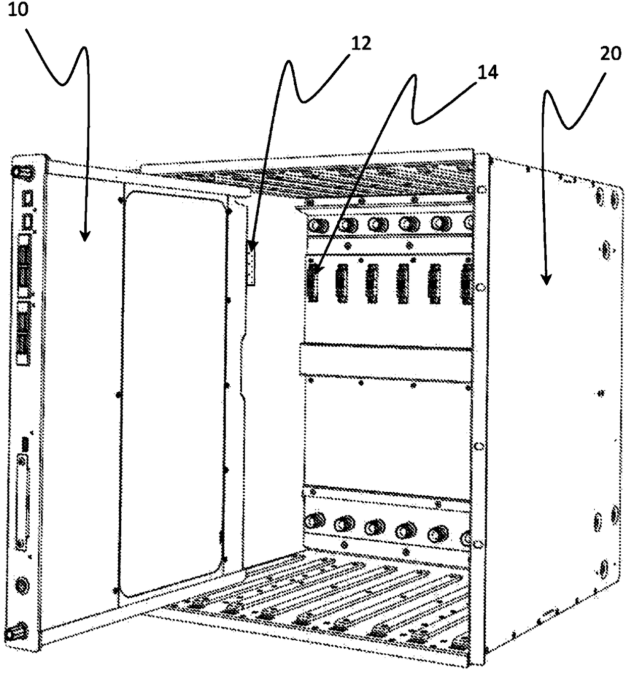
[0101] First refer to figure 1 , a cabinet or rack 20 is shown. Racks of this type may be used, for example, in networked computing environments to house large numbers of data servers.

[0102] A cabinet or rack 20 is arranged to house one or more cooling systems 10 (also referred to as cooling blades or fins). Each cooling system 10 houses one or more heat generating electrical components operating within the network. For example, each cooling system 10 may accommodate a motherboard, a central processing unit (CPU), and memory modules to form a data server. Even during normal operation, the electrical components can dissipate significant amounts of heat, so the cooling system is configured to efficiently and effectively remove heat from the vicinity of the electrical components.

[0103] The cabinet 20 is configured with power connectors 14 arranged to correspond to the reciprocal power connectors 12 arranged at the rear surface of each cooling system 10 . The power conne...


PUM


Abstract

A cooling system for cooling of a heat generating electrical component, in particular to reduce the likelihood of overheating of electrical components or chemical breakdown of coolant fluid. The cooling system has a coolant liquid to absorb excess energy from the heat generating electrical component, the coolant liquid having an energy input threshold above which chemical breakdown of the coolantliquid occurs. A cooling module defines a volume containing the coolant liquid, wherein the heat generating electrical component is mounted within the volume and immersed in the coolant liquid. A power input is arranged to supply power into the cooling module to the heat generating electrical component, and a power regulator is provided external to the volume of the cooling module and connected tothe power input so as to regulate the power supplied into the cooling module. Cooling systems are also described having coolant liquid comprising dissolved oxygen, having at least one element arranged within the volume comprising aluminium and / or aluminium oxide, and / or having a sealed volume with at least one seal which opens at a predetermined pressure or temperature corresponding to a temperature below the temperature at which the coolant liquid breaks down.

Description

technical field [0001] The present invention relates to an immersion cooling system providing increased safety during operation. The cooling system enhances safety by regulating electrical power input to electrical components immersed in the coolant fluid within the cooling system and also by providing various mechanisms that can stop components from overheating and allow the products of chemical decomposition of the coolant fluid to be neutralized . In particular, the invention is suitable for cooling electronic computer components, such as motherboards, processors or memory modules. Background technique [0002] Many types of electrical components generate heat during operation. In particular, electronic computer components such as motherboards, central processing units (CPUs) and memory modules dissipate significant amounts of heat during use. Heating electrical components to high temperatures can cause damage, affect performance, or create a safety hazard. Therefore,...

Claims


Application Information

Patent Timeline
Patent Type & Authority Applications(China)
IPC IPC(8): H05K7/20
CPCH05K7/20236H05K7/203H05K7/20772H05K7/20809H05K7/1492H05K7/20245H05K7/20263H05K7/209
Inventor 彼得·霍普顿基思·迪金詹森·本特尼尔·埃德蒙兹大卫·阿莫斯
Owner 爱思欧托普集团有限公司
Why Eureka
Try Eureka