Wall body environment-friendly dismounting device

An environmental protection, wall technology, applied in building maintenance, construction, building construction, etc., can solve the problems of inconvenient manual demolition, loud dust and noise, and troublesome follow-up processing.

Active Publication Date: 2018-07-31
江苏中柢建设集团有限公司
View PDF7 Cites 1 Cited by
  • Summary
  • Abstract
  • Description
  • Claims
  • Application Information

AI Technical Summary

Problems solved by technology

[0002] Due to the lack of open space resources available for infrastructure construction, it is inevitable to demolish the old infrastructure first, and then build new residences and other facilities on the original space. The demolition of the original old facilities generally uses There are two ways, one is demolition by hand or with the help of other construction machinery, but because the original infrastructure is generally reinforced concrete structure, it is extremely inconvenient to do manual demolition, so the general demolition period is long, and dust and noise are generated, which seriously affects The daily life and construction progress of nearby residents, another demolition method is blasting. Although blasting can quickly demolish the building, a large amount of soot will be generated during the blasting process, and the remaining reinforced concrete will be mixed in the building. At the same time, the follow-up treatment is also relatively troublesome. Therefore, it is necessary to design a kind of wall environmental protection demolition device that can separate the cement and the steel structure during the wall demolition process, and the noise generated during the construction process is small, and there is no smoke.

Method used


Image

  • Wall body environment-friendly dismounting device
  • Wall body environment-friendly dismounting device
  • Wall body environment-friendly dismounting device

Examples


Embodiment Construction

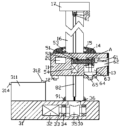
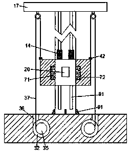
[0022] Such as Figure 1-8As shown, a kind of wall environmental protection dismantling device of the present invention, comprises base 31, the elevating device that is arranged inside described base 31 symmetrically front and back, is arranged on the upright column 16 of described base 31 upper end face, is arranged on described upright column 16 The wall demolition body 11, the wall demolition mechanism arranged on the right side of the wall demolition body 11 and the anti-drop device 20 arranged on the left side of the column 16 are arranged on the right side of the wall demolition body 11 The wall removal mechanism includes an opening 62 set in the right end of the wall removal main body 11, the right end of the wall removal main body 11 is provided with a cotton-like body 13, and the upper end wall of the opening 62 is provided with front and rear A plurality of high-pressure water guns 61, the lower end of the left side of the opening 62 is provided with a discharge cham...


PUM


Abstract

The invention discloses a wall body environment-friendly dismounting device. The wall body environment-friendly dismounting device comprises a base, lifting devices arranged in the base in a front-back symmetry mode, a vertical column arranged on the upper end face of the base, a wall surface dismounting main body arranged on the vertical column, a wall surface dismounting mechanism arranged on the right side of the wall surface dismounting main body and a falling-preventing device arranged on the left side of the vertical column. The wall surface dismounting mechanism arranged on the right side of the wall surface dismounting main body comprises an opening cavity formed in the right end face of the wall surface dismounting main body, a sponge-shaped body is arranged on the right end faceof the wall surface dismounting main body, and a plurality of high-pressure water guns arrayed in the front-back direction are arranged on the upper end wall of the opening cavity. An unloading cavityis formed in the lower end of the left side of the opening cavity, an unloading opening is formed in the lower end of the unloading cavity, and a stirring motor is fixedly arranged on the front sideof the middle of the wall surface dismounting main body. A rotating cavity is arranged at the upper end of the stirring motor, and a driving rotary shaft is arranged on the left side of the rotating cavity.

Description

technical field [0001] The invention relates to the technical field of building construction, in particular to an environment-friendly demolition device for walls. Background technique [0002] Due to the lack of open space resources available for infrastructure construction, it is inevitable to demolish the old infrastructure first, and then build new residences and other facilities on the original space. The demolition of the original old facilities generally uses There are two ways, one is demolition by hand or with the help of other construction machinery, but because the original infrastructure is generally reinforced concrete structure, it is extremely inconvenient to do manual demolition, so the general demolition period is long, and dust and noise are generated, which seriously affects The daily life and construction progress of nearby residents, another demolition method is blasting. Although blasting can quickly demolish the building, a large amount of soot will be...

Claims


Application Information

Patent Timeline
Patent Type & Authority Applications(China)
IPC IPC(8): E04G23/08
CPCE04G23/081
Inventor 阮哲栋
Owner 江苏中柢建设集团有限公司
Why Eureka
Try Eureka