Evaporation source evaporation rate control equipment, method and device and storage medium
A technology of evaporation rate and evaporation source, which is applied in the fields of devices and storage media, evaporation rate control equipment, and methods, and can solve problems such as the influence of film material evaporation rate and the effective control of evaporation rate of difficult evaporation sources, etc.
- Summary
- Abstract
- Description
- Claims
- Application Information
AI Technical Summary
Problems solved by technology
Method used
Image
Examples
Embodiment 1
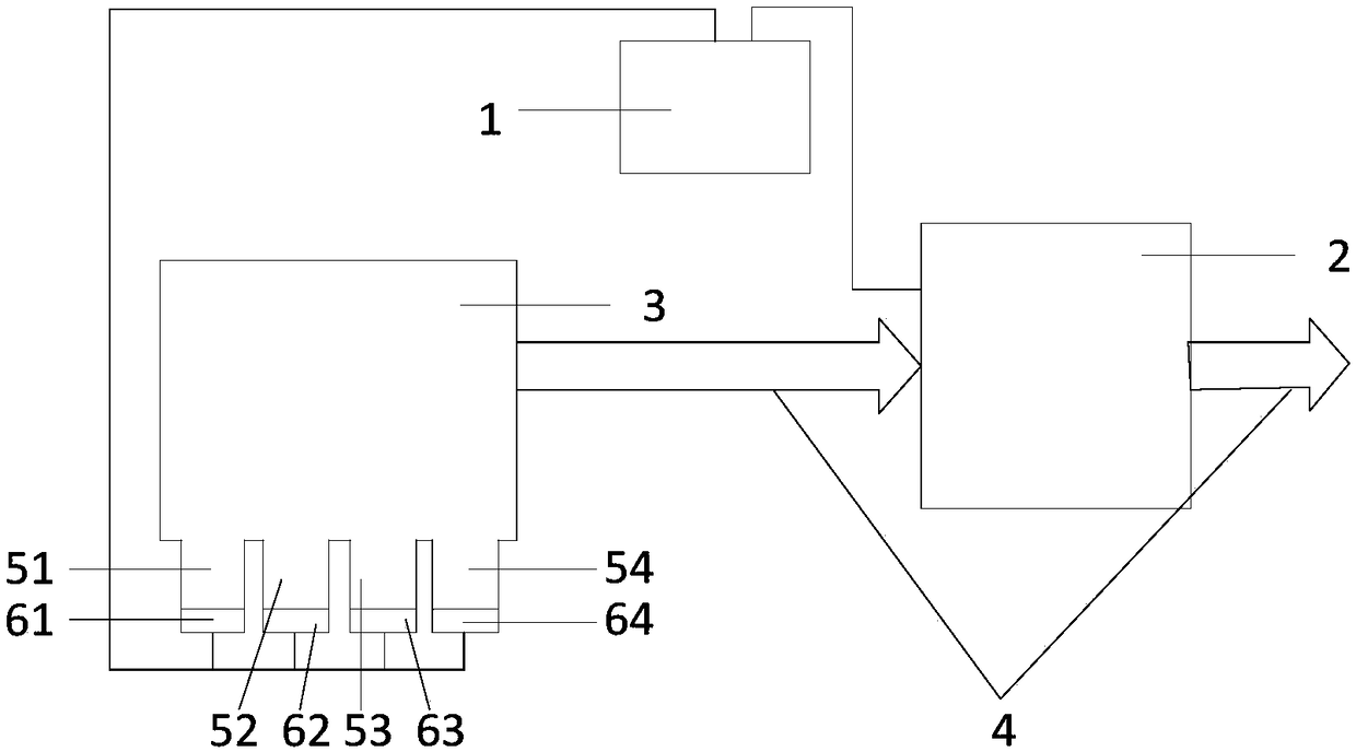
[0059] figure 1 It is a structural schematic diagram of the evaporation rate control device for the evaporation source provided in Embodiment 1 of the present invention. Such as figure 1 As shown, the device includes a connected controller 1 and an online collector 2 .
[0060] Wherein, the online collector 2 is used to collect the coating parameters of the substrate, and send the coating parameters to the controller 1 . Wherein, the coating parameters include film thickness and / or element ratio.
[0061]Optionally, the online acquisition instrument 2 is set on the substrate output transmission line 4 connected to the CIGS chamber 3 , and is used for collecting coating parameters of the substrate on the substrate output transmission line 4 . Wherein, the CIGS chamber 3 is used to accommodate the evaporation source.
[0062] After the substrate is coated in the CIGS chamber 3 , the substrate is transported to the on-line collector 2 by the sheet output transmission line 4 c...
Embodiment 2
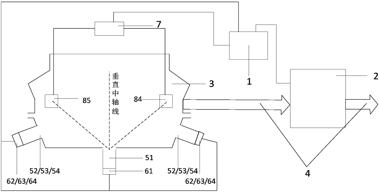
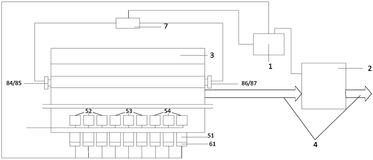
[0076] This embodiment is further optimized on the basis of the foregoing embodiments. Figure 2a It is the left view of the CIGS chamber provided by Embodiment 2 of the present invention, Figure 2b It is the front view of the CIGS chamber provided by the second embodiment of the present invention. combine Figure 2a and Figure 2b , the device also includes a film thickness controller 7 and a collection component.
[0077] The acquisition part is used to collect the oscillation frequency caused by the coating of the first target coating element; the film thickness controller is respectively connected with the controller and the acquisition part, and is used to obtain the variation of the oscillation frequency from the acquisition part, according to the change measuring the thickness of the first target coating element, and sending the thickness of the first target coating element to the controller.
[0078] Optionally, collection components such as Figure 2c As shown, ...
Embodiment 3
[0094] On the basis of the above embodiments, the device further includes a sampling component 9 and an offline collector 10 . Figure 3a It is the left view of the CIGS chamber provided by Embodiment 3 of the present invention, Figure 3b It is the front view of the CIGS chamber provided by Embodiment 3 of the present invention. combine Figure 3a and Figure 3b , the device includes a controller 1 , an online collector 2 , a film thickness controller 7 , a collection component, a sampling component 9 and an offline collector 10 . Wherein, the relevant descriptions of the controller 1, the online acquisition instrument 2, the film thickness control instrument 7 and the acquisition components are detailed in the above-mentioned embodiments, and will not be repeated here.
[0095] On the outer wall of the CIGS chamber 3 above each metal evaporation source, at least one sampling component 9 is respectively arranged for plating the second target coating element. Wherein, the ...
PUM
 Abstract
Description
Claims
Application Information
 - Generate Ideas
- Intellectual Property
- Life Sciences
- Materials
- Tech Scout
- Unparalleled Data Quality
- Higher Quality Content
- 60% Fewer Hallucinations
Browse by: Latest US Patents, China's latest patents, Technical Efficacy Thesaurus, Application Domain, Technology Topic, Popular Technical Reports.
© 2025 PatSnap. All rights reserved.Legal|Privacy policy|Modern Slavery Act Transparency Statement|Sitemap|About US| Contact US: help@patsnap.com


