Eureka AIR delivers breakthrough ideas for toughest innovation challenges, trusted by R&D personnel around the world.

A controllable evaporative micro burner utilizing waste heat of flue gas

A micro-combustion, flue gas waste heat technology, applied in the burner, combustion type, combustion method and other directions, can solve the problem of neglecting the thermal stability of the working wall of the micro-burner and the reasonable working wall temperature, and the increase of the burner surface area to volume ratio , combustion is difficult to operate continuously and efficiently, to achieve the effect of increasing residence time, small relative temperature fluctuation, and improving work efficiency

Active Publication Date: 2020-01-10
HEFEI UNIV OF TECH
View PDF5 Cites 0 Cited by
  • Summary
  • Abstract
  • Description
  • Claims
  • Application Information

AI Technical Summary

Problems solved by technology

Micro-scale combustion has different characteristics from conventional-scale combustion, which are mainly reflected in three aspects. First, the ratio of surface area to volume of the burner increases, which is two to three orders of magnitude higher than that of traditional burners. The increase in the ratio of surface area to volume causes Increased heat loss
The second is that the residence time is short due to the reduction in size, and it is more difficult to completely burn the fuel. The combustion organization is not good, and a large amount of fuel will be discharged directly with the exhaust gas without burning, reducing the combustion efficiency.
Based on the above three points, it is difficult to operate continuously and efficiently at the micro scale
The existing various burners, through the reasonable design of the internal circulation structure and the design of the combustion method, have improved the residence time of the fuel to a certain extent and increased the heat exchange efficiency of the burner, but neglected the work of the micro burner. Wall thermal stability and reasonable working wall temperature

Method used


Image

  • A controllable evaporative micro burner utilizing waste heat of flue gas

Examples


Embodiment 1

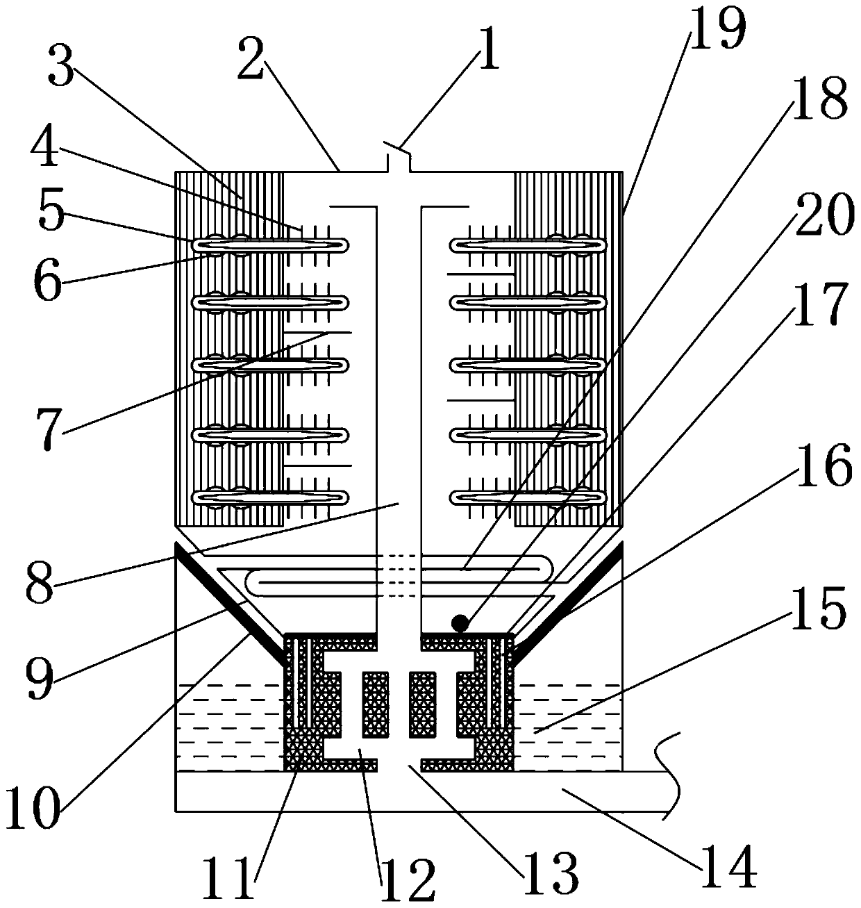
[0025] like figure 1 As shown, a controllable evaporative miniature burner utilizing waste heat of flue gas includes a burner outer cylinder 2, an evaporation core 11 is provided on the inner surface of the lower end of the burner outer cylinder 2, and the evaporation core 11 and the side of the burner outer cylinder 2 An oil tank 15 is formed between the walls, a steam channel 16 is arranged inside the evaporation core 11, a steel wire mesh 17 is fixedly installed on the upper surface of the evaporation core 11, and an igniter 20 is arranged above the steel wire mesh 17;

[0026] A combustion chamber 9 is arranged above the evaporating core 11, and a regenerator 3 is fixedly installed above the combustion chamber 9 close to the inner surface of the side wall of the outer cylinder 2 of the burner. The outer wall of the outer cylinder 2 of the burner corresponding to the regenerator 3 is The working wall surface 19 of the burner, the inside of the regenerator 3 is fixedly inser...


PUM


Abstract

The invention relates to a controllable evaporative micro-burner using waste heat of flue gas. The controllable evaporative micro-burner using the waste heat of the flue gas comprises a burner outer cylinder, an evaporation core is arranged on the inner surface of the lower end of the burner outer cylinder, an oil tank is formed between the evaporation core and the side wall of the burner outer cylinder, the evaporation core is internally provided with a steam channel, a steel wire mesh is fixedly installed on the upper end face of the evaporation core, and a flame lighter is arranged on the upper part of the steel wire mesh; a burning chamber is arranged on the upper part of the evaporation core, heat accumulators are fixedly installed on the positions, close to the inner surface of the side wall of the burner outer cylinder, above the burning chamber, the outer wall of the burner outer cylinder corresponding to the heat accumulators is the burner working wall surface, and heat pipesare fixedly inserted in the heat accumulators. According to the controllable evaporative micro-burner using the waste heat of the flue gas, it can be ensured that the temperature of the burner workingwall surface is stable, the degree of fuel burning can be increased, and use of thermal energy is increased.

Description

technical field [0001] The invention belongs to the technical field of energy combustion and utilization, and in particular relates to a controllable evaporative micro burner utilizing waste heat of flue gas. Background technique [0002] The micro-thermo-photovoltaic system is one of the emerging new micro-power systems, and the most important component in the micro-thermo-photovoltaic system is a micro-burner that can make liquid hydrocarbon fuels burn stably and efficiently. Micro-scale combustion has different characteristics from conventional-scale combustion, which are mainly reflected in three aspects. First, the ratio of surface area to volume of the burner increases, which is two to three orders of magnitude higher than that of traditional burners. The increase in the ratio of surface area to volume causes Heat loss increases. The second is that the reduced size results in a short residence time, making it more difficult to completely burn the fuel, and the combust...

Claims


Application Information

Patent Timeline
Patent Type & Authority Patents(China)
IPC IPC(8): F23D11/22F23D11/44
CPCF23D11/22F23D11/44
Inventor 马培勇林英坤孙海韵王世玉马美娜邢献军
Owner HEFEI UNIV OF TECH
Why Eureka
Eureka Blog
Learn More