
Material bin anti-bridge device and working method thereof

An anti-bridging and silo technology, applied in the silo anti-bridging device and its working field, can solve the problems of high labor intensity, hollow bottom, and lower material level in the silo, so as to increase safety and controllability , Realize continuous operation and increase the dispersion effect

Pending Publication Date: 2018-07-31
夏友亮 +1
View PDF9 Cites 0 Cited by
  • Summary
  • Abstract
  • Description
  • Claims
  • Application Information

AI Technical Summary

Problems solved by technology

The material will expand when heated in the warehouse, and will be compacted under a certain weight, causing kinks and interweaving with each other, which is very easy to cause overlapping and bridging phenomenon, resulting in hollow bottom, and the material cannot be discharged from the warehouse. normal continuous production
After bridging occurs, it usually takes several hours to process and is labor-intensive. In production, the material level in the silo is generally artificially reduced, resulting in a decrease in the actual utilization rate and retention time of the silo, and affecting the process reaction effect
[0003] At present, in order to prevent the phenomenon of material bridging, the mechanical structure of the silo generally adopts a truncated conical circular silo and a square silo with a trapezoidal cross-section. Although it has some effects on preventing bridging, it cannot be effectively solved. Often due to Produce bridging and affect continuous production

Method used


Image

  • Material bin anti-bridge device and working method thereof
  • Material bin anti-bridge device and working method thereof
  • Material bin anti-bridge device and working method thereof

Examples


Embodiment 1

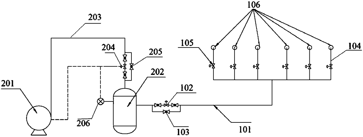
[0030] Embodiment 1: as figure 1 As shown, the silo anti-bridging device of the present invention consists of a spraying device and an air supply device for providing high-pressure gas.

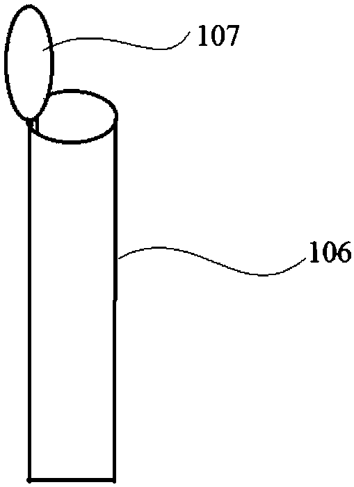
[0031] The injection device includes a first connecting pipe 101, a second electromagnetic valve 102 arranged on the first connecting pipe and connected to a Siemens PLC controller in communication, a first bypass circuit 103, and several bypasses communicated with the gas outlet of the first connecting pipe. The branch pipe 104, the first electromagnetic valve 105 communicated with the controller arranged on the bypass branch pipe, the injection port 106 communicated with the bypass branch pipe, and the cover 107 arranged on the injection port, the injection ports are arranged around the hopper circle.

[0032] The air supply device includes a high-pressure air pump 201 connected in communication with the controller, a high-pressure air storage tank 202, a second connecting pipe 203 connecti...

Embodiment 2

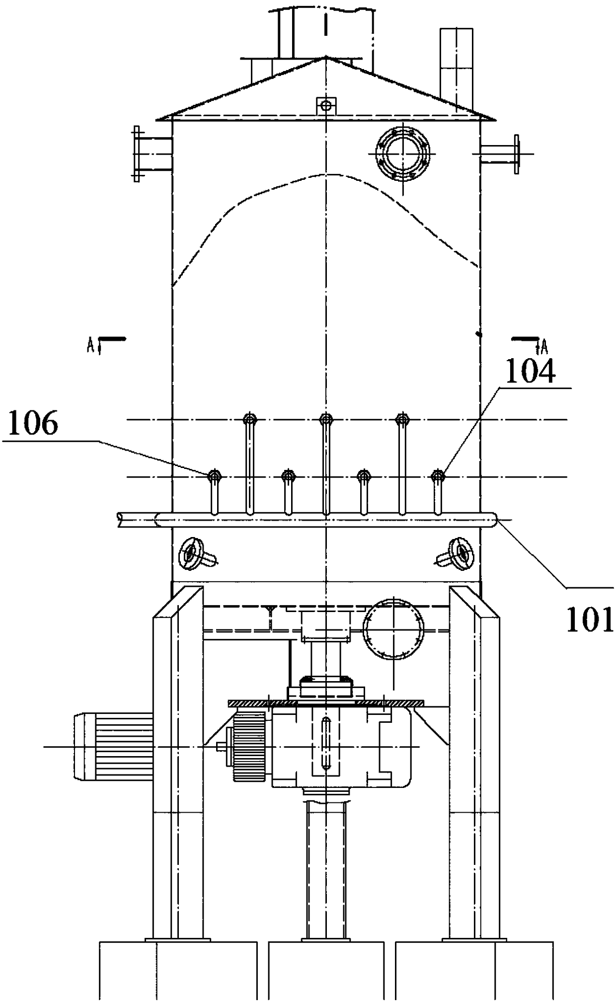
[0033] Embodiment 2: as image 3 , Figure 4 , Figure 5 with Image 6 As shown, the silo anti-bridging device of the present invention consists of a spraying device and an air supply device for providing high-pressure gas.

[0034] The injection device includes a first connecting pipe 101, a second electromagnetic valve 102, a first bypass circuit 103, and a number of bypass branch pipes connected to the gas outlet of the first connecting pipe, which are arranged on the first connecting pipe and communicate with the Siemens PLC controller. 104. The first electromagnetic valve 105, which is arranged on the bypass branch pipe and communicates with the controller, the injection port 106 communicated with the bypass branch pipe, and the cover 107 arranged on the injection port. The injection ports are arranged in two circles around the silo. Floor.

[0035] The air supply device includes a high-pressure air pump 201 connected in communication with the controller, a high-press...


PUM


Abstract

The invention discloses a material bin anti-bridge device and a working method thereof. The material bin anti-bridge device comprises an air supply device, a first connecting pipe and a plurality of injection ports, wherein the air supply device is used for providing high-pressure gas, the first connecting pipe is connected with the air outlet of the air supply device, and the injection ports usedfor high-pressure gas spraying are formed in the air outlet end of the first connecting pipe. According to the device, accumulated materials in a material bin can be intermittently impacted through apreset program, a lap joint material layer is damaged, and the phenomenon of material bridging can be prevented; and even if bridging is formed, the problem can be quickly solved, the processing timecan be shortened, and the labor intensity is reduced.

Description

technical field [0001] The invention relates to processing equipment and its working method, in particular to a material bin bridging prevention device in the processing equipment and its working method. Background technique [0002] The pulping process of plant fiber raw materials requires moistening and chemical treatment to achieve fiber softening, and then in the subsequent refining process, more complete fibers can be separated, long fiber components can be increased, and the physical strength of the pulp can be improved. , while reducing the energy consumption of refining. Moisturizing, softening and chemical treatment require a certain residence and reaction time and a silo with a certain volume to realize slurry storage and retention. The material will expand when heated in the warehouse, and will be compacted under a certain weight, causing kinks and interweaving with each other, which is very easy to cause overlapping and bridging phenomenon, resulting in hollow b...

Claims


Application Information

Patent Timeline
Patent Type & Authority Applications(China)
IPC IPC(8): B65D88/70
CPCB65D88/70
Inventor 夏友亮陈伟伟曹堪洲范刚华
Owner 夏友亮
Learn More