
Spot-jet cooling ring and wheel hub mould with spot-jet cooling ring

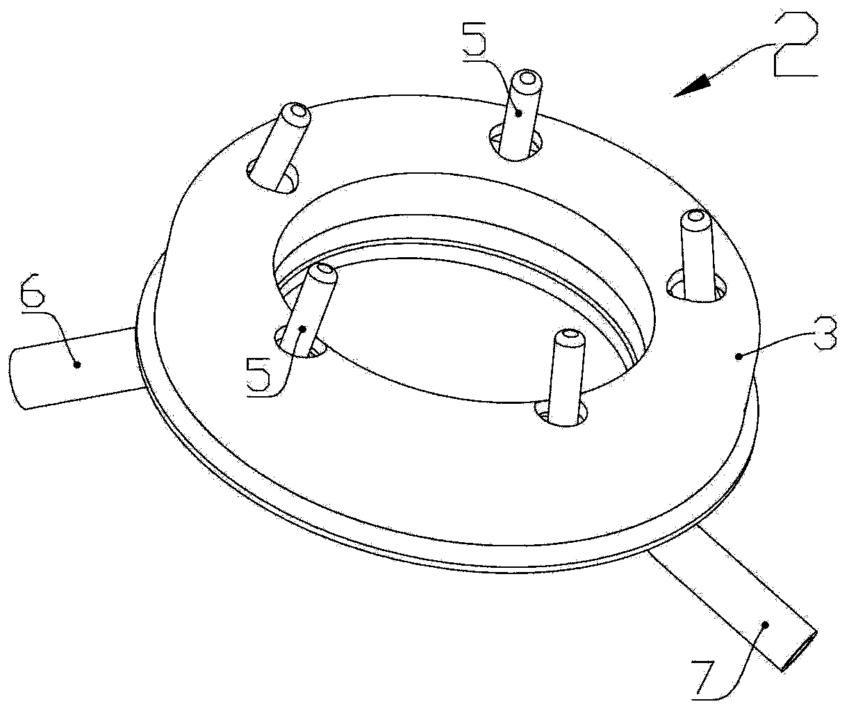
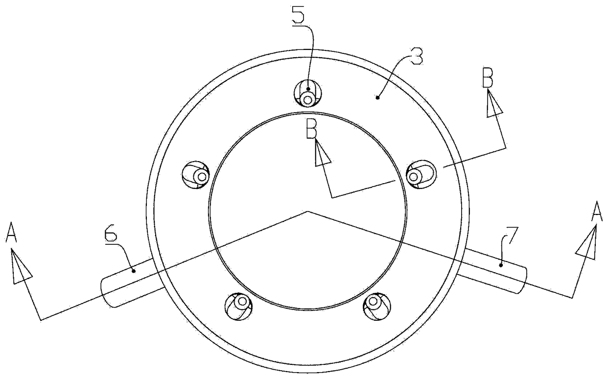
A technology of cooling ring and spot spraying, which is applied in the direction of manufacturing tools, casting molding equipment, casting molds, etc., can solve the problems of cumbersome processing, complex water flow pipeline structure, and increased processing costs of multi-point combined cooling devices, and achieve simplified processing operations, The effect of reducing processing cost and simple structure

Active Publication Date: 2018-07-31
FOSHAN NANHAI SUPERBAND MOLD
View PDF11 Cites 1 Cited by
  • Summary
  • Abstract
  • Description
  • Claims
  • Application Information

AI Technical Summary

Problems solved by technology

After careful study of the structure of the multi-point combined cooling device, it can be found that the structure of the water flow pipes arranged on it is extremely complicated, and it is necessary to drill vertical and horizontal points for each cooling point on the cooling seat 9. The staggered water inlet holes 22, return water holes 25, and return water channels 18 are very cumbersome to process, which will undoubtedly increase the processing cost of the multi-point combined cooling device

Method used


Image

  • Spot-jet cooling ring and wheel hub mould with spot-jet cooling ring
  • Spot-jet cooling ring and wheel hub mould with spot-jet cooling ring
  • Spot-jet cooling ring and wheel hub mould with spot-jet cooling ring

Examples


Embodiment Construction

[0024] The structure of the spot-spray cooling ring and the wheel hub mold applied to the technical solution of the present invention will be further described below in conjunction with the accompanying drawings.

[0025] Such as figure 1As shown, the hub mold 100 using the spot spray cooling ring 2 includes an upper mold 1 and a lower mold 12 separated from the upper and lower, and a side mold 11 arranged between the upper mold 1 and the lower mold 12. The upper mold 1, the lower mold 12 and the side mold 11 enclose the hub cavity 10, and the lower mold 12 is provided with a gate 13 for inputting raw material melt, and the gate 13 communicates with the hub cavity 10, At least one pair of protruding pillars 121 (also known as PCD pillars) are arranged on the upper peripheral wall of the gate 13 , and all the protruding pillars 121 extend upward and are arranged around the gate 13 . On the lower side wall of the lower mold 12, there is a closed ring-shaped accommodation pit (i...


PUM


Abstract

The invention discloses a spot-jet cooling ring and a wheel hub mould with the spot-jet cooling ring. The spot-jet cooling ring comprises a closed-ring-shaped outer shell, and the outer shell is provided with an upper shell and a lower shell, wherein the upper shell and the lower shell are split and can form an annular inner cavity after being vertically closed in an opposite mode. A refrigerant conveying inner pipe arranged around a central ring core of the outer shell is contained in the annular inner cavity, and a feeding hole for communicating with an external refrigerant source is formedin the refrigerant conveying inner pipe. A refrigerant channel is formed between the outer shell wall of the outer shell and the outer pipe wall of the refrigerant conveying inner pipe, the outer shell is provided with a discharging hole and a transition through hole which are formed in different shell wall areas, and the discharging hole communicates with the refrigerant channel. The spot-jet cooling ring further comprises a refrigerant jet pipe which is sleeved with the transition through hole in a penetrating mode, an inner end pipe opening of the refrigerant jet pipe communicates with therefrigerant conveying inner pipe, an outer end pipe opening of the refrigerant jet pipe is arranged outside the outer shell, and backflow clearances are formed between the hole inner wall of the transition through hole and the pipe outer wall of the refrigerant jet pipe and communicate with the refrigerant channel. According to the spot-jet cooling ring, an internal flow channel structure and machining operation are simplified, and the machining cost is reduced.

Description

technical field [0001] The invention relates to a cooling device that can be applied to a mould, and the cooling device adopts a point-spray cooling method to cool hot nodes on the mould. The invention also relates to a wheel hub mold using the point-spray cooling ring. Background technique [0002] In order to speed up the cooling rate of the casting, a cooling device is often provided in the casting mold. The applicant pays attention to a multi-point combined cooling device disclosed in Chinese utility model patent ZL201120209943.7, which includes an annular cooling seat 9 on which two circulating water channels (18, 19) are arranged. ), the lower circulating water channel is set as the water inlet channel 19, and the upper circulating water channel is set as the return water channel 18, the water inlet channel 19 is connected with the cooling medium liquid source of the casting machine through the water inlet pipe 6, and the return water channel 18 passes through The wa...

Claims


Application Information

Patent Timeline
IPC IPC(8): B22C9/28B22D27/04
CPCB22C9/28B22D27/04
Inventor 简伟文吴概陈振明陈庆勋
Owner FOSHAN NANHAI SUPERBAND MOLD
Learn More