
Rotor, motor, reinforcing ring tooling and mounting method thereof

A technology of reinforcing rings and tooling, applied in the manufacture of stator/rotor bodies, magnetic circuit rotating parts, magnetic circuit shape/style/structure, etc., can solve the problem of increasing the cost of motor materials, increasing the overall size of the motor, and easily deforming the rotor and other issues to achieve the effects of improving flexibility, applicability, reducing production costs, and simple locking effect

Active Publication Date: 2018-07-27
BEIJING GOLDWIND SCI & CREATION WINDPOWER EQUIP CO LTD
View PDF4 Cites 5 Cited by
  • Summary
  • Abstract
  • Description
  • Claims
  • Application Information

AI Technical Summary

Problems solved by technology

However, since the rotor yoke is a thin-walled part with a large diameter, the rotor is easily deformed during the machining, transportation, and installation of the motor.
[0004] In order to solve the problem of deformation of the rotor during machining, transportation and installation, one way in the current prior art is to weld a permanent reinforcement ring on the outer wall of the rotor yoke, which not only increases the overall size of the motor, but also increases the The material cost of the motor
Another way is to use a temporary reinforcement ring welded on the outer wall of the rotor yoke, although this will not increase the material cost of the motor, but the rotor needs to be cut, polished, anti-corrosion and other operations, so the processing cost is higher

Method used


Image

  • Rotor, motor, reinforcing ring tooling and mounting method thereof
  • Rotor, motor, reinforcing ring tooling and mounting method thereof
  • Rotor, motor, reinforcing ring tooling and mounting method thereof

Examples


Embodiment Construction

[0047] Features and exemplary embodiments of various aspects of the invention will be described in detail below. In the following detailed description, numerous specific details are set forth in order to provide a thorough understanding of the present invention. It will be apparent, however, to one skilled in the art that the present invention may be practiced without some of these specific details. The following description of the embodiments is only to provide a better understanding of the present invention by showing examples of the present invention. In the drawings and the following description, at least some well-known structures and techniques have not been shown in order to avoid unnecessarily obscuring the present invention; and, for clarity, the dimensions of some structures may have been exaggerated. The same reference numerals in the drawings denote the same or similar structures, and thus their detailed descriptions will be omitted. Furthermore, the features, st...


PUM


Abstract

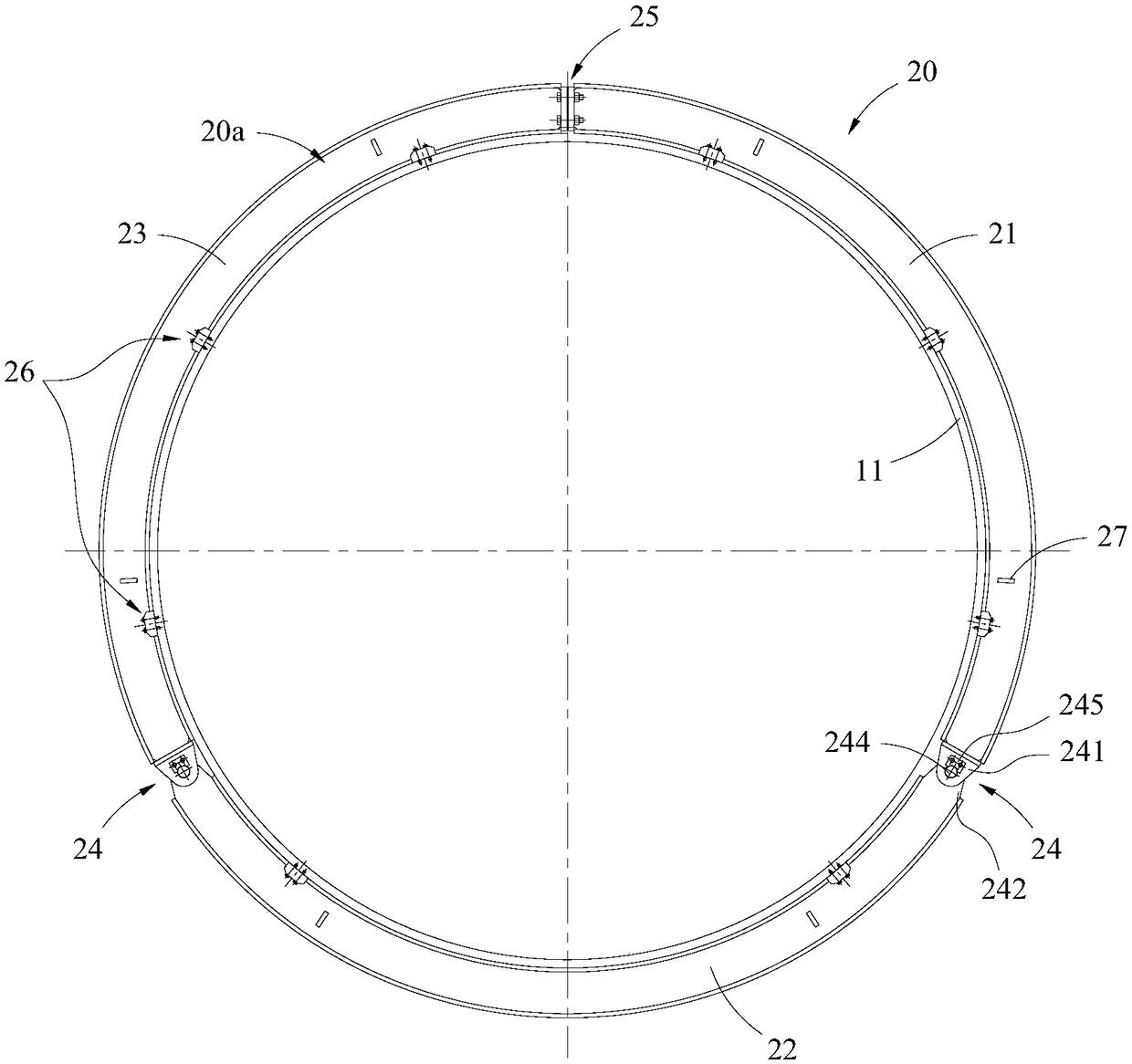
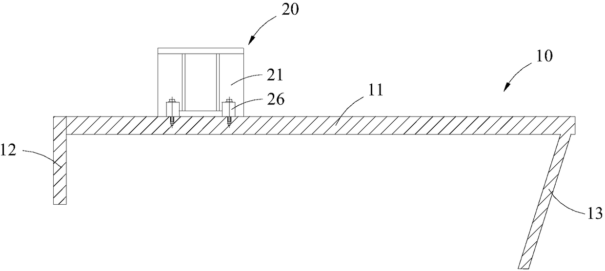
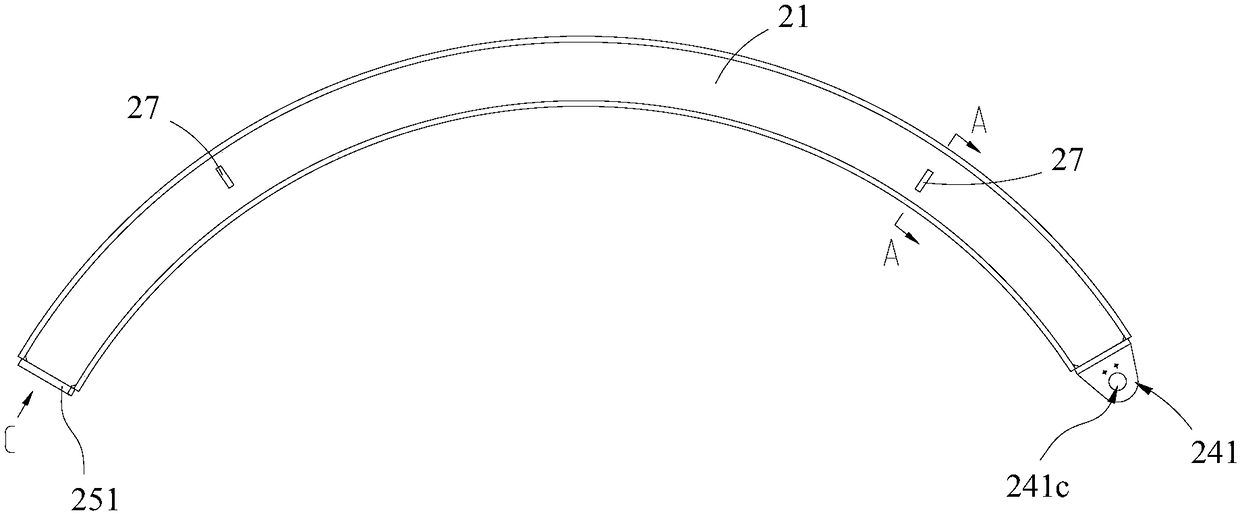
The invention provides a rotor, a motor, a reinforcing ring tooling and a mounting method thereof. The reinforcing ring tooling can be mounted at the periphery of the rotor of the motor, the reinforcing ring tooling comprises more than two split components and more than two connecting parts, wherein more than two connecting parts are corresponding to more than two split components, and more than two split components are mutually connected through more than two connecting parts to form an annular body; at least two connecting parts in more than two connecting parts are movable connection parts,and the corresponding split components are mutually and movably connected through the movable connection parts, thereby enabling the reinforcing ring tooling to detachably connect with the peripheryof the rotor. Therefore, one or more aims of preventing the rotor from deforming in the transportation mounting process of the motor, reducing the manufacturing cost of the motor, reducing the transportation and mounting of the motor and like operation difficulties can be realized.

Description

technical field [0001] The invention relates to the field of motors, in particular to a rotor, a motor, a reinforcing ring tooling and an installation method thereof. Background technique [0002] At present, because the low-speed large-diameter motor has many advantages, it has been widely used. For example, in the field of wind power generation, direct-drive wind turbines are widely used because they have many advantages such as high efficiency at low wind speeds, low noise, long life, and low operation and maintenance costs. However, as the power of the wind power generator increases, the volume and weight of the motor in the direct drive wind power generator also increases. [0003] For example, for a permanent magnet synchronous motor, it is mainly composed of a stator and a rotor. For an outer rotor motor, the stator is fixed at the center of the motor, and the rotor is sleeved on the outer periphery of the stator so that the rotor can rotate around the central axis o...

Claims


Application Information

Patent Timeline
Patent Type & Authority Applications(China)
IPC IPC(8): H02K1/22H02K15/02
CPCH02K1/22H02K15/02Y02E10/72H02K1/24H02K1/28
Inventor 李延慧王栋杨景超
Owner BEIJING GOLDWIND SCI & CREATION WINDPOWER EQUIP CO LTD
Learn More