Bridge surface crack detection device

A detection device, a technology for surface cracks, used in measurement devices, elasticity testing, machine/structural component testing, etc., which can solve problems such as efficiency that is easily affected by subjective factors, easy to be affected by weather changes, and difficult to guarantee results. , to achieve the effect of convenient and targeted treatment, reducing labor intensity and operation risk, and reducing dependence

Inactive Publication Date: 2018-07-27
广州晟达机械设计有限公司
View PDF5 Cites 10 Cited by
  • Summary
  • Abstract
  • Description
  • Claims
  • Application Information

AI Technical Summary

Problems solved by technology

[0003] At present, bridge inspection mainly relies on the manual observation of the staff sitting in the hanging basket of the bridge inspection vehicle close to the bridge surface to be inspected. It mainly relies on personal experience for visual inspection. Given the inspection results, it is easily affected by subjective factors, and the efficiency is low and the risk is high. At the same time, because the hanging basket should be close to the bridge surface to be inspected, when the hanging basket encounters the bridge pier and the avoidance platform, the bridge inspection vehicle must stop running, retract the hanging basket, avoid the bridge pier and the avoidance platform, and then extend to the working position. The work efficiency is very low; another way is to use vision technology to inspect the surface of bridges with long-distance observation devices or other mounted devices on the ground, mostly to detect highway bridges with short distances in cities, but this method is vulnerable to weather changes Influence, it is difficult to guarantee the effect in practical application

Method used


Image

  • Bridge surface crack detection device
  • Bridge surface crack detection device
  • Bridge surface crack detection device

Examples


Embodiment Construction

[0015] The present invention will be further described in conjunction with the following application scenarios.

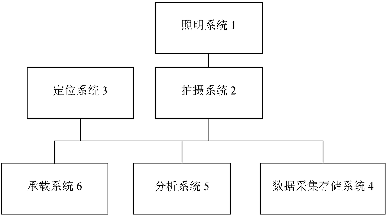
[0016] see figure 1 , a bridge surface crack detection device, comprising: a lighting system 1, used to provide lighting for the bridge surface to be detected; a shooting system 2, installed in a protective cover, for cooperating with the lighting system 1 to collect bridge surface images; positioning System 3 is installed on the carrying system 6 to determine the position of the defect on the bridge; the data acquisition and storage system 4 is used to receive the bridge surface image and defect location information collected in real time and record them on the hard disk; the analysis system 5 uses To carry out real-time analysis on the bridge surface images collected by the shooting system 2, and detect whether there are cracks on the bridge surface; the carrying system 6, including the wall climbing robot, is used to carry the lighting system 1, the shooting sys...


PUM


Abstract

The invention provides a bridge surface crack detection device, which comprises an illumination system used for providing illumination for the surface of a to-be-detected bridge; a shooting system arranged in a protection cover and used for being matched with the illumination system to collect a bridge surface image; a positioning system installed on a bearing system and used for determining the position of a defect on the bridge; a data acquisition and storage system used for receiving the bridge surface image and the defect positioning information collected in real time and recording the bridge surface image and the defect positioning information in a hard disk; an analysis system used for analyzing the bridge surface image acquired by the shooting system in real time, and judging whether cracks exist on the surface of the bridge or not; and the bearing system. The bearing system comprises a wall climbing robot is used for bearing the illumination system, the shooting system and thepositioning system. Meanwhile, the bearing system moves on the surface of the bridge.

Description

technical field [0001] The invention relates to the technical field of bridge safety monitoring, in particular to a bridge surface crack detection device. Background technique [0002] The appearance of cracks on the bridge surface is a concentrated expression of internal damage reaching a certain degree of danger, and it is the most obvious signal of structural danger of the bridge. When the width of the crack reaches more than 0.2mm, external water vapor can easily enter the interior to accelerate the corrosion of steel bars, which may directly damage the bridge. Integrality greatly reduces the bearing capacity of the bridge and affects the safety of roads and railways on the bridge. Therefore, capturing and inspecting bridge surface cracks in time is of great significance for predicting or discovering engineering dangers, ensuring reliable operation of bridges and prolonging the service life of bridges. [0003] At present, bridge inspection mainly relies on the manual o...

Claims


Application Information

Patent Timeline
Patent Type & Authority Applications(China)
IPC IPC(8): G01M5/00
CPCG01M5/0008G01M5/0033
Inventor 黄信文
Owner 广州晟达机械设计有限公司
Why Eureka
Try Eureka