A shock absorber damping regulating valve

A damping adjustment and shock absorber technology, which is applied in the field of damping adjustment valves, can solve the problems of high cost of magneto-rheological fluid, reduced maneuverability, and difficult control, so as to expand the range of damping adjustment, facilitate manufacturing and installation, and reduce manufacturing costs Effect

Inactive Publication Date: 2019-12-31
JIANGSU UNIV
View PDF7 Cites 0 Cited by
  • Summary
  • Abstract
  • Description
  • Claims
  • Application Information

AI Technical Summary

Problems solved by technology

When traditional passive shock absorbers face this contradiction, they often can only adopt a "compromise" solution to deal with complex road conditions and different road conditions with a fixed damping coefficient. Driving habits, often resulting in a decrease in comfort and reduced handling
[0003] Therefore, the popular semi-active and active suspension technologies in recent years can adjust the stiffness and damping of the suspension in real time according to the road conditions, so that the suspension is in the best vibration reduction state and improve the driving comfort and safety of the car. These technologies need to add various sensors, motors, and electromagnets, with complex structures and high costs
For example, patents with application numbers 201010552262.0 and 201110072795.3 have invented a shock absorber, which is only related to the displacement of the piston and has nothing to do with the speed of movement, and only provides stepwise damping adjustment in a specific stroke section, and the damping adjustment range is relatively large. Small; magnetorheological shock absorbers invented by patents with application numbers 200510060298.6 and 201510213044.7. Although this type of shock absorber can provide stepless damping, it requires more supporting equipment, and the cost of magnetorheological fluid is relatively high; application Patents No. 201410098849.7, 201610970549.2, 201310475991.4 and 201710499846 require the installation of additional sensors, motors or electromagnets. The structure is complex, the control is difficult, and the cost is high.

Method used


Image

  • A shock absorber damping regulating valve
  • A shock absorber damping regulating valve
  • A shock absorber damping regulating valve

Examples


Embodiment Construction

[0016] The following embodiments given in conjunction with the accompanying drawings illustrate the present invention in further detail, but are not intended to limit the present invention.

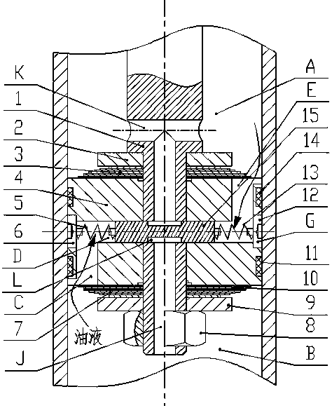
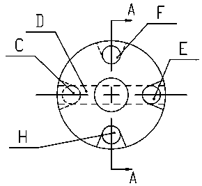
[0017] Such as Figure 1 to Figure 2 As shown, the embodiment of the present invention discloses a shock absorber damping regulating valve mainly comprising: a piston rod 1, a piston assembly and a valve assembly. The piston assembly includes a piston 4, a left spring 5, a left spring positioning seat 6, a lower sealing ring 10, a lower sealing ring 11, a right spring positioning seat 12, a right spring 13, an upper sealing ring 14, etc.; the valve assembly includes an upper limit Bit block 2, circulation valve group 3, recovery valve group 7, fastening nut 8, lower limit block 9, throttle valve core 15. The piston rod 1 includes a first piston rod 1-1 and a second piston rod 1-2. The piston 4 is installed on the second piston rod 1-2. The piston 4 divides the shock absorber working cyli...


PUM


Abstract

The invention relates to a damping regulating valve for a shock absorber. The damping regulating valve mainly comprises piston rods, limiting blocks, a valve plate group, a piston, springs, spring positioning seats, a fastening nut, a throttle valve core, sealing rings and the like. The valve can be applied to single-cylinder shock absorbers and double-cylinder shock absorbers. The throttle valvecore installed in the piston automatically senses road surface vibration and automatically switches to a suitable damping value. The damping characteristic of the shock absorber equipped with the damping regulating valve automatically changes with the driving condition, and the steplessly adjustable function and the wide adjusting range are realized, so that a vehicle has excellent smoothness andmaneuverability; and meanwhile the damping regulating valve has the beneficial effects of being simple in structure, sensitive in response, high in reliability, free of sensors and power sources, lowin cost and the like.

Description

technical field [0001] The invention relates to a damping regulating valve which can be used in the field of single cylinder and double cylinder shock absorbers, in particular to a damping regulating valve of the shock absorber which can change the damping characteristics of the shock absorber according to the working conditions. Background technique [0002] The driving comfort and safety of a car are a pair of natural contradictions. Comfort requires the shock absorber to provide a softer damping force, while driving safety requires the shock absorber to provide a larger damping force. When the up and down movement speed of the suspension is high and the acceleration is high, the damping is required to be large; when the suspension is moving up and down at a low speed and the acceleration is small, a small damping is required so that the vehicle has better driving comfort and manipulative. When traditional passive shock absorbers face this contradiction, they often can on...

Claims


Application Information

Patent Timeline
Patent Type & Authority Patents(China)
IPC IPC(8): F16F9/34F16F9/512
CPCF16F9/34F16F9/5126F16F2228/066
Inventor 谢方伟曹金鑫丁二名王登帅万快弟
Owner JIANGSU UNIV
Why Eureka
Try Eureka