
A lane-changing driving device for mine car filling

A driving device and mine car technology, which is applied to roads, tracks, movable tracks, etc., can solve the problems of track change device failure, no mine car turning, mine car wheel damage, etc., to improve efficiency and precision, reduce costs, and drive The effect of simple device structure

Inactive Publication Date: 2019-08-02
CHINA UNIV OF MINING & TECH
View PDF4 Cites 0 Cited by
  • Summary
  • Abstract
  • Description
  • Claims
  • Application Information

AI Technical Summary

Problems solved by technology

[0002] In mine operations, mine cars are mainly used for the transportation of coal and other materials, and are generally pulled by locomotives or winches. However, in narrow mines, due to limited space, it is difficult for locomotives or winches to pull mine cars for filling operations. There is also not enough room for the minecart to turn around
[0003] The current mine car lane change mainly realizes the mechanical change of the mine car from one track to another track through the promotion of hydraulic or pneumatic devices, which will cause certain damage to the wheels of the mine car; It will block the path to push the track change, which will lead to the failure of the track change device
[0004] In some places, for the flexibility of the mine car operation, a motor drive is installed on each mine car, which results in an increase in the cost of the mine car and maintenance costs, and the mine car only needs to be driven separately in some areas. Will be pulled by locomotive or winch, resulting in idleness of independent drives
[0005] Some auxiliary mine car filling devices only realize the propulsion and pushing of the mine car when filling, but do not realize the accurate positioning of the mine car, cannot be well matched with the existing filling system, and cannot accurately run the mine car to the designated area after filling and other Docking of mining cars or traction locomotives

Method used


Image

  • A lane-changing driving device for mine car filling
  • A lane-changing driving device for mine car filling
  • A lane-changing driving device for mine car filling

Examples


Embodiment Construction

[0036] The present invention will be further explained below in conjunction with the accompanying drawings.

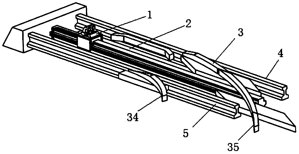
[0037] Such as figure 1 , 5 , 7, 8, and 9, a lane-changing driving device for mine car filling of the present invention includes a mine car track, a transition track, a driving guide rail 2, a driving device 1 and a track changing device 3.

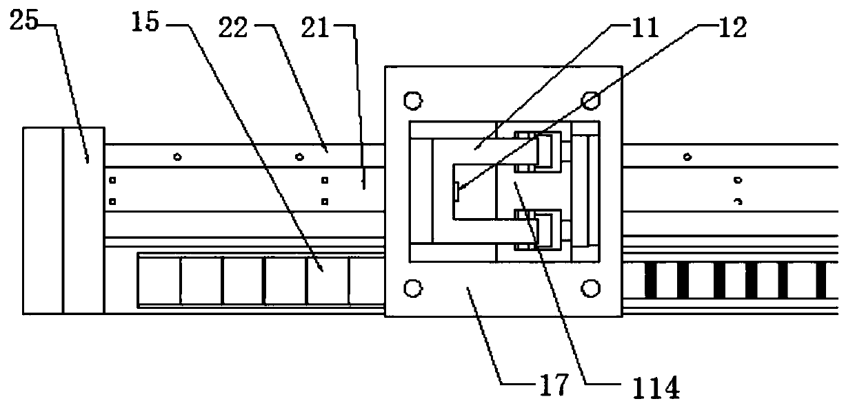
[0038] The driving guide rail 2 is arranged between the left side rail 4 and the right side rail 5 of the mine car track, the driving guide rail 1 includes a roller guide rail 21 and an engaging guide rail, the roller guide rail 21 is provided with a wheel groove, and the engaging guide rail is provided with a bar tooth 24 .

[0039] The driving device 1 includes a sliding platform 17 arranged above the roller guide rail 21 and the engaging guide rail, the top of the sliding platform 17 is provided with a mine wheel axle clamping mechanism, and the mine wheel axle clamping mechanism is used to clamp or loosen the mine wheel axle...


PUM


Abstract

The invention discloses a lane changing driving device for mine car packing. The device comprises a mine car track, a transition track, a driving guide rail, a driving device and a track changing device; the driving guide rail is arranged between a left track and a right track of the mine car track, the driving guide rail comprises a roller guide rail and a meshed guide rail, the roller guide railis provided with a wheel groove, and the meshed guide rail is provided with strip-shaped teeth; the driving device comprises a sliding platform arranged above the roller guide rail and the meshed guide rail, a mine car axle clamping mechanism is arranged on the top of the sliding platform, the bottom of the sliding platform is provided with rollers and meshed gears driven by a driving motor; thetrack changing device comprises a front end deflection track, a rear end deflection track, a front-end cushion track, a rear end cushion track, a rear end potension meter and a front end potesion meter; the transition track comprises an inner transition track and an outer transition track which are arranged on the outer side of the right track of the mine car track, and connection or disconnectionbetween the mine car track and the transition track is achieved through the track changing device. The defect of narrow mine track mine car track changing driving is overcome, and the mine car partial section driving is achieved.

Description

technical field [0001] The invention relates to a lane-changing driving device for a mine car, in particular to a track-changing driving device for a mine car filling in a narrow mine road. Background technique [0002] In mine operations, mine cars are mainly used for the transportation of coal and other materials, and are generally pulled by locomotives or winches, but in narrow mines, due to limited space, it is difficult for locomotives or winches to pull mine cars and perform stuffing operations. There is also not enough room to turn the direction of the minecart. [0003] The current mine car lane change mainly realizes the mechanical change of the mine car from one track to another through the promotion of hydraulic or pneumatic devices, which will cause certain damage to the wheels of the mine car; and because the mine car track often has cinder accumulation, It will cause obstruction to the path for promoting the track change, thereby causing the failure of the tra...

Claims


Application Information

Patent Timeline
Patent Type & Authority Patents(China)
IPC IPC(8): E01B23/06E21F13/02
CPCE01B23/06E21F13/025
Inventor 李中凯苗磊宋英侯昆峰殷文卫
Owner CHINA UNIV OF MINING & TECH
Learn More